
Introduction
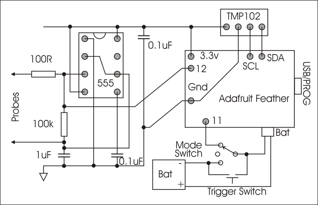
This page describes the electronics connected with the 3D-printed soil moisture tester. Below is the circuit diagram. (Back to construction.)
How the circuit works
The 555 timer chip is set up to produce regular square-shaped pulses (square wave). So if you measured the voltage at the probes it would either be about 3.3 volts (the supply voltage) or zero volts. The frequency or rate of these pulses depends on the 1 uF capacitor and the resistance at the probes (through which the capacitor is charged and discharged). When the probes are inserted into soil, they “see” a resistance which depends to a large extent on the water content (the concentration of various salts is a factor but for our purposes we will ignore!) The lower the resistance, the faster the pulses (as the capacitor charges and discharges faster). The pulses are fed into the Adafruit Feather through pin 12 and the software (see later) is set up to count the pulses in a given period. Using this value, the software outputs on the OLED display, an evaluation of the soil dampness.
(Two reasons I use this method of measuring resistance is that it lends itself to making permanently connected remote sensors – the pulse rate method will not be dependent on the resistance of the cable connecting the sensors to a central unit and also I fancy that the soil may see the voltage at the probes as being a sort of alternating current which will avoid polarisation at the probes – the generation of gas which can increase the resistance seen by the probes – and corrosion of the probes.)
The Mode Switch
There is something I call the Mode Switch. This is double throw, centre off toggle switch. In one position it overrides the trigger and keeps the device on continuously. In the other, this position is detected by the Feather as pin 11 is connected to ground (pin 11 is normally high as the software activates the internal pull-up resistor). In this mode, the software retains the display corresponding to the wettest measurement made since the trigger began to be pressed. This might be useful if delving int undergrowth where the OLED screen can’t be easily seen. If the switch is in the off position the device is activated normally by pressing the trigger.
More details of the 555 timer
More details of the operation of this fabulously useful 555 chip (it has been around for almost 50 years and, according to Wikipedia, it is the most popular integrated circuit ever manufactured!). If the output pin (3) is high (3.3 v) The 1 uF capacitor charges through the resistance across the probes (actually the resistance across the probes in series with the 100 R resistance and in parallel with the 100 k resistor – the 100 R prevents a dead short which could upset things and the 100 k prevents an almost infinite resistance when the probes are not in soil which can cause the software to pause while it waits for a pulse that never comes!)
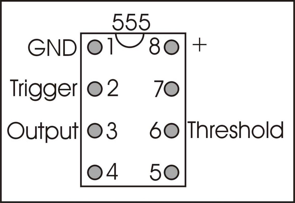
Anyway, notice pins 2 and 6 are connected to the junction of the resistance combination and the 1 uF capacitor. When the capacitor charges up to 2/3 of the supply voltage (detected by pin 6, “threshold”) the output flips to zero. Then the capacitor discharges through the same combination of resistances until the voltage reaches 1/3 of supply voltage (detected by pin 2, “trigger”) and so on. Further information on the 555 is available on the Web or in an excellent book IC 555 Projects by EA Parr – still available after over 40 years!
PCB design
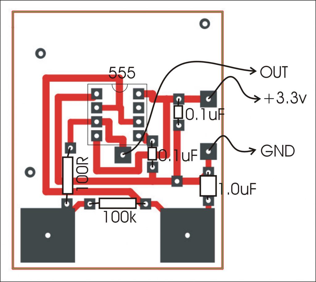
The picture above shows the PCB overlay for this project. There is a slight variation in the position of the 100R resistor compared to the circuit diagram. Also the PCB I produced for this project does not look exactly like the picture above as I originally designed a more complex circuit using two 555s in one IC which didn’t work well and proved to be unnecessarily complex. So the PCB I fitted uses one half of the double chip (a 556).
I design my PCBs using DesignSpark PCB software (which is free). I print the design onto inkjet transparent film and use this in an ultraviolet light box with photosensitized PCB material. I then develop and etch the PCB material and drill the pads with a Dremel type drill. You can find more details of how I do it on my old web site at http://www.mr-r.co.uk/makingpcb1.html.
The PCB has to have a cut out to accommodate the moulding which takes the M4 bolt which keeps the two halves of the case together.
Components
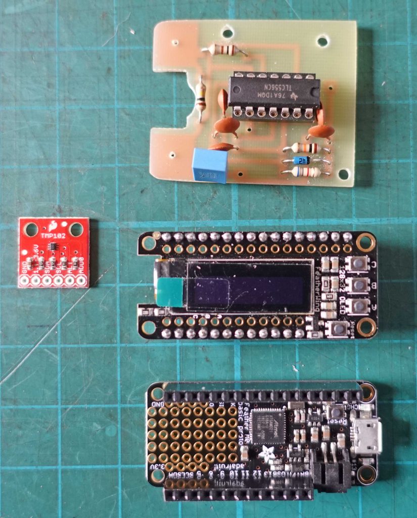
The picture above shows the main electronic components. At the top is the PCB (as mentioned, this is a different version modified to function as described in the text above). Below that the Feather Wing OLED display and below that the Feather M0 with the prototyping area (replaces the WiFi module etc. on other Feathers). The module on the red PCB is the TMP102 from Sparkfun which measures temperature. This connects to the Feather by I2C.
Connecting it up
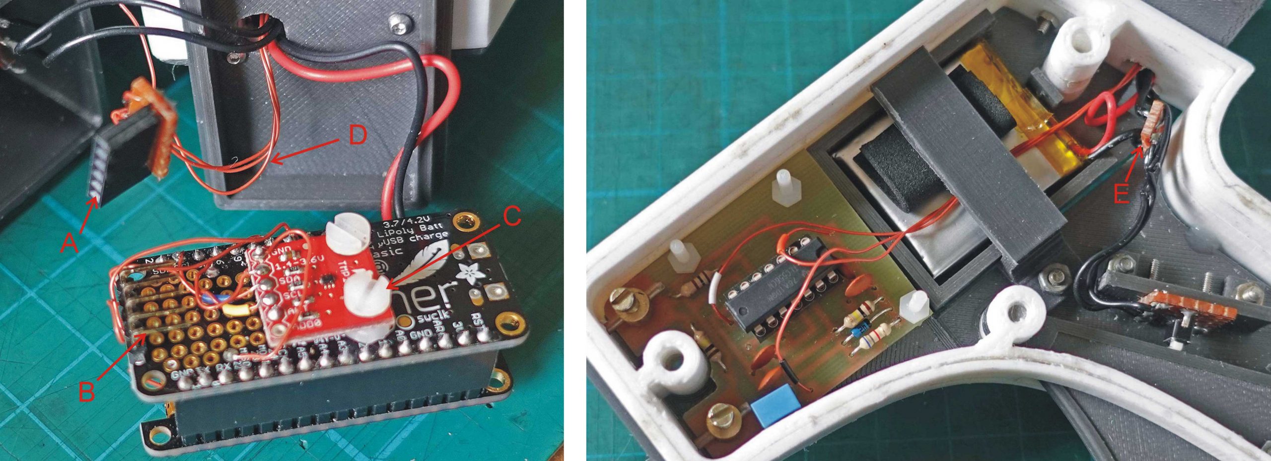
The picture above, left, shows how I have used male and female headers to form a plug and socket system to connect the Feather. A is a five-way female header soldered onto a small piece of strip board (Veroboard) to enable wires to be soldered on. The wires, D, are 30 awg (0.05 mm2) wire wrapping wire that I have had knocking around for a very log time. This is still available. Designed to be used for wire wrapping prototype circuits, this wire is very flexible, silver-plated copper with very heat-resistant insulation and ideal when you don’t want wire to take up much space. You need a wire wrapping tool to reliably strip off the insulation. 30 awg stranded “hook up” wire is an alternative such as this.
B points to the right-angle headers soldered onto the prototyping area of the Feather. The TMP102 module is soldered to a header which is in turn soldered to the prototyping area. The M 2.5 nylon screws, C, are cut to just keep the Feather/OLED/TMP102 assembly touching the front panel. A piece of thin neoprene foam in the back of the case provides a little springiness.
The picture above, right, shows the assembly within the pistol-grip section of the project. As per the circuit diagram, the negative lead of the battery is cut. This is bridged by the trigger switch and mode selector switch within the box containing the Feather etc. In order to connect the various wires together, I have used a small piece of strip board, E, which (rather inelegantly) floats in the space without being screwed down (but it can’t go anywhere!) You can also see a small blob of Araldite fixing the trigger “chassis” in place, a piece of foam under the battery clip to prevent it rattling around, and the circuit board (not quite like the version given above as already mentioned). You can also see a few gaps where the inner and outer parts of the side did not quite come together!
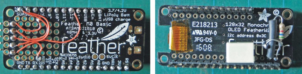
The picture, above left, shows how the header is connected to the various pins on the Feather using the wire wrapping wire (the arrangement shown is not the one in the project but very similar). It should be noted that the protyping pads on the Feather are not connected to anything including other pads except for the four 3.3V and the four ground pads.
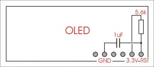
The picture on the right, above, shows the resistor and capacitor combination that I have found necessary to hold the OLED reset low long enough, on power up, for the rest of the system to sort itself out. (See the circuit diagram left.)