
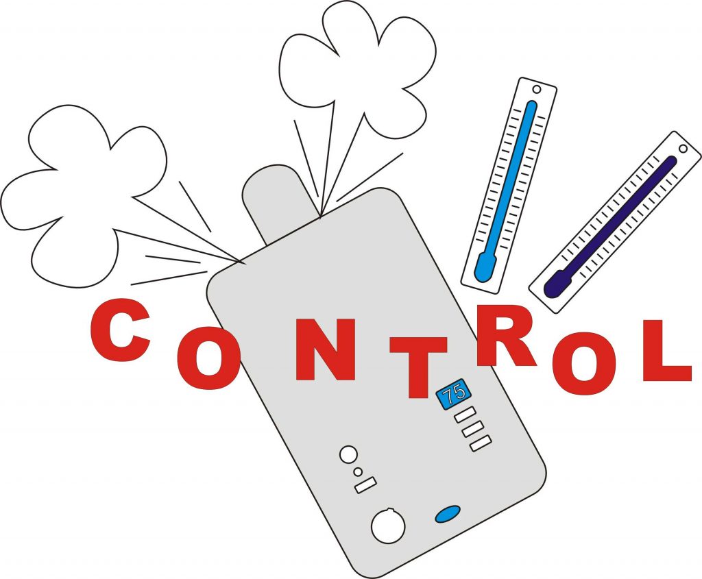
Background
I discovered recently that if the returning water in a condensing boiler system is above 55 degC (some say above 50 degC) then the water vapour in the exhaust gasses is not properly condensing and the latent heat of condensation cannot be utilised and the boiler loses about 10% efficiency.
You can tell, apparently, that the boiler is operating properly in condensing mode if it pumps out visible water vapour.
For years I had been running the boiler at maximum (75 degC flow temperature). The boiler does not indicate the return temperature so I decided to make a device to measure the flow and return temperatures and display them on an LCD screen.
Spoiler alert!
To jump ahead, later I built a device to rotate the boiler temperature control knob under remote / computer control (using a servo some Arduino Unos and a Raspberry Pi). The idea was to run the boiler hot first thing in the morning then at night and when the hot water tank needed heating. The system would take into account room temperature and other factors such as outside temperature, room usage etc.
Control temperature – save £s – hopefully…
After noticing that running the boiler at a much lower temperature than I had used previously and still feel warmth in the house, I decided to use the Arduino Uno to measure the various temperatures and connect this to a Raspberry Pi via the standard USB connection so that the Pi could program the Arduino and, once it was running, receive data and issue commands over serial. The Arduino would control a small radio control type servo to adjust the boiler temperature via the boiler control knob. The control program on the Pi would be written in Python / TkInter and I could access it remotely on a PC, tablet, phone etc. via VNC.
Things didn’t turn out quite as I had originally planned. Something went wrong with one of the tmp102s in spite of my having used them in many other projects (I probably accidentally shorted it in some way). I decided it was time to choose something else and went for the DS18B20 sensor which can be obtained in a neat 6mm stainless tube with a built in cable. These sensors work on the 1-wire communication protocol. You can connect as many as you like to one pin. Each sensor is uniquely identifiable. I bought two from Pimoroni which are guaranteed to meet the full specification. I then bought five more on Amazon for a fraction of the price. Reviews suggested some of the cheaper versions might not be up to the full spec but they all seemed OK. There is a bit of fiddling needed to identify which sensor the software has decided is which but otherwise the sensors are great.
I drilled small aluminium blocks to take the sensors, filed a curve in the blocks so they fitted snugly on the flow and return boiler pipes and used Jubilee clips to hold them on. I added some silicon heat sink grease to ensure good conduction and wrapped some insulation round the whole thing. I also drilled a hole though the wall and poked a sensor though to give me an outside temperature.
Temperature display
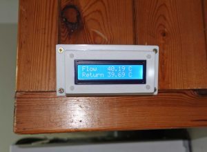
Next, I added an LCD to display the values. This requires six Arduino pins which is a lot! Later when I added the Ethernet Shield, I didn’t have enough pins spare. The answer was to use the Adafruit LCD Backpack which plugs into the back of the LCD unit and communicates with the Arduino over I2C which releases the previously used six pins.
Mechanical construction
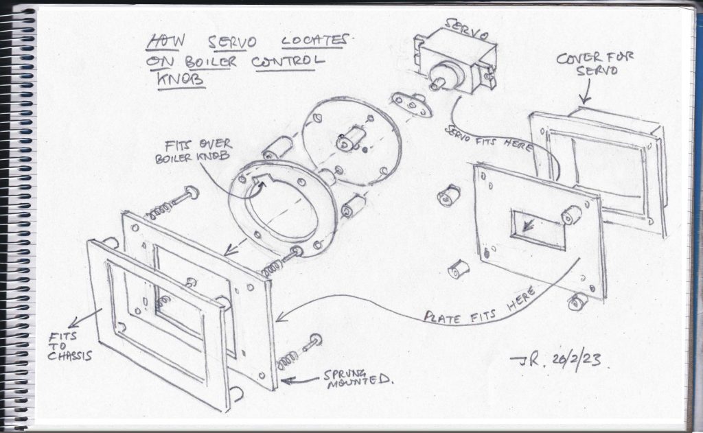
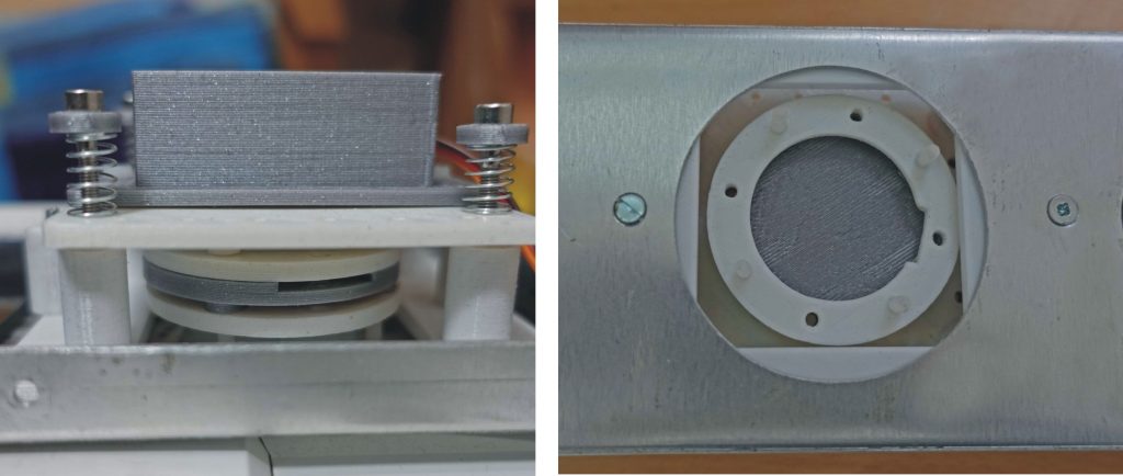
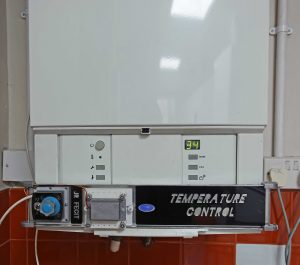
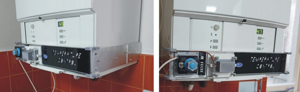
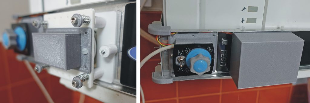
The mechanical construction required something to clamp onto the boiler and engage the temperature knob. I didn’t want to drill holes in the boiler casing for obvious reasons, so I relied on the power of magnets (see pictures). To engage the knob, I 3D-printed a ring which would fit over the knob with a small cut out which would, in turn, fit over the bulge in the knob. I linked this to a corresponding disc fitted to the servo using springs so the ring was held securely onto the boiler control knob. The springs were as weak as possible so as not to put any strain on the control knob mechanism.
The servo and knob engagement assembly was attached to a 22 gauge (approx) metal chassis which fits round the boiler. I made it in several pieces so I could adjust it on assembly to ensure a good fit. The chassis rests on a convenient moulding at the bottom of the boiler which hinges the cover to the controls (which I have unclipped). At the rear I have made a couple of small tabs which just locate the chassis at the back of the boiler. The chassis is made rigid at its front by means of small angles formed top and bottom but flexible at the sides so it can be sprung into place. Bar magnets on both sides hold it in place.
I’ve added some decorative bits of perspex on the front which serve no useful purpose except labelling the potentiometer control and the switch!
Electronics
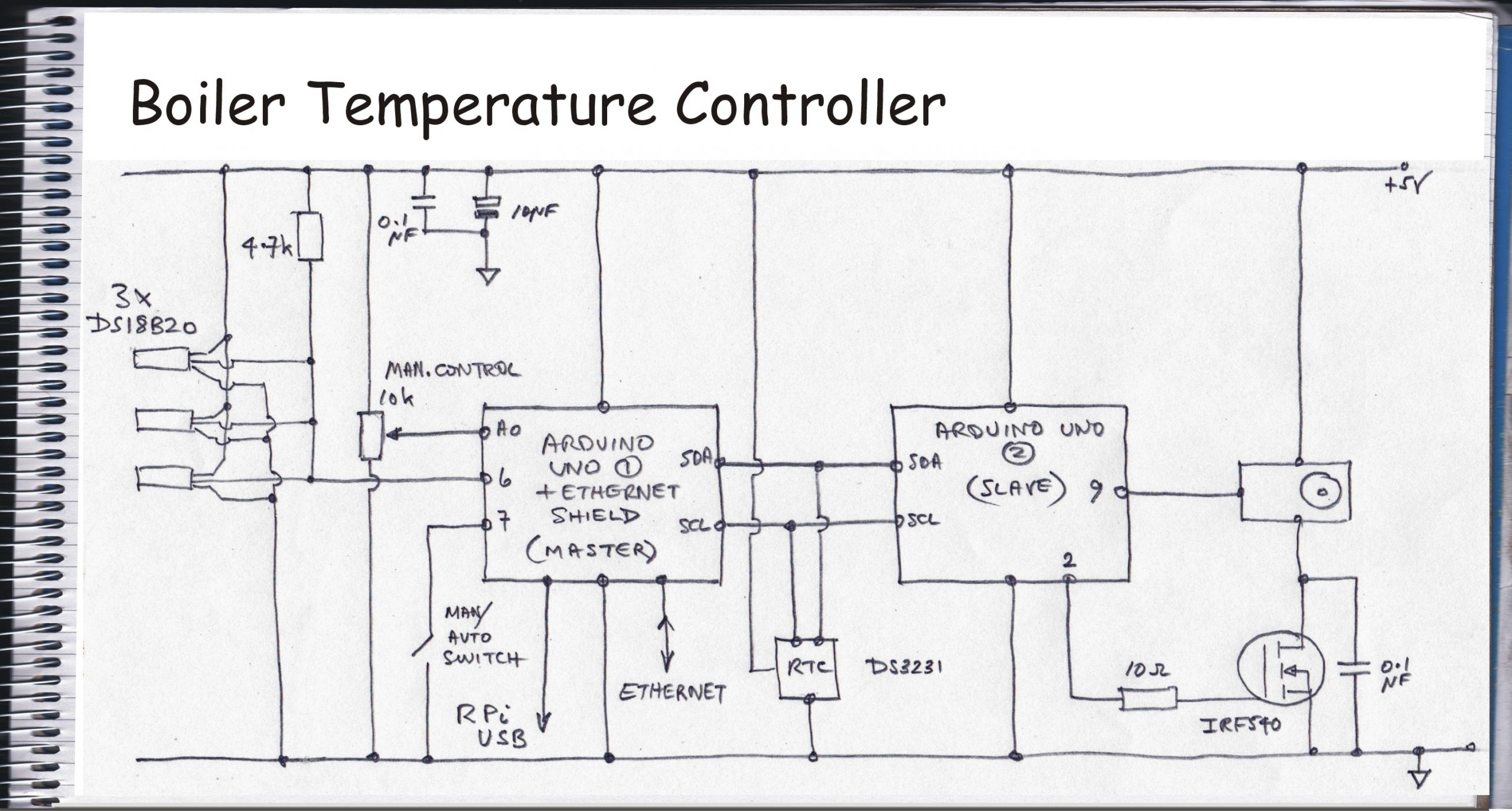
I added a DS3231 real time clock and a servo to the Arduino so that the servo would be made to operate at times stored on the Arduino. This is where the next problem manifested itself. The servo did not complete its programmed movement. This was no doubt due to the Arduino trying to do too many things at once. Perhaps interrupts could be made to solve this, however, I decided to use a slave Arduino Uno to control the servo with the original Arduino acting as master. The connection is by I2C and this worked just fine.
Next I tried to use the serial connection to send commands from the Pi to the Arduino. There seems to be a problem with serial and the Uno as serial comms seems to trigger a reset. This can be overcome by connecting a 10uF capacitor between reset and ground (See here.). I was then able to receive data over serial. However, I had a problem trying to send from the Pi to the Uno and the result seemed to be that the bootloader was overwritten as I could no longer program the Arduino. I could burn a new bootloader (using yet another Arduino) but subsequently, it was deja-vu all over again!
I decided to abandon serial (leaving it just for programming and the Arduino IDE Serial Monitor tool) and use the UDP data transfer protocol (as I have done with my greenhouse controller and boiler timer etc.)
The location of the boiler is separated from the router by a two foot granite wall so Wi-Fi is weak and unreliable. Fortunately, I laid an Ethernet cable between the router and the boiler timer when I installed it a number of years ago. All I needed was an Ethernet switch connect the Raspberry Pi and the Arduino Uno using an Ethernet Shield. Genuine Ethernet Shields may be unavailable but the Han Run HR911105A clone can be had. This worked just fine as long as any errors are trapped at the Python end. I had never used an Ethernet switch before and hadn’t realised that you just connect it to the router by any of the sockets and then plug you various devices into any of the other sockets and it just works. Simples!
Back to the electronics, I added a facility to manually alter the boiler temperature in the form of a potentiometer and a manual/automatic toggle switch connected to an analog and a digital pin respectively.
I’ve added a transistor to enable power to the servo to be cut off when it’s not being required to move. Without this, the servo sometimes makes slight noises (chatter?) which, I think, corresponds to slight uncertainties in the mechanisms/electronics of the servo. You can’t feel any movement of the servo output shaft so it’s not affecting the boiler but it probably wears the servo motor’s brushes.
Constructing the electronics
From a electronics construction point of view, I felt that since there were very few components apart from the Arduinos, I could get away with a Veroboard (strip board) circuit board rather than a dedicated pcb. The Arduino’s headers are a bit annoying in that one group of eight don’t fit into a 0.1 inch matrix like the rest and so make connection to Veroboard inconvenient. Fortunately, I didn’t need to use any of the pins in this group ( 0 – 7) so I just soldered headers to the Veroboard corresponding to the other positions on the Arduino. I made further connections using DuPont connectors and headers etc. Hopefully the pictures will give a little more detail (one picture worth etc. etc.)
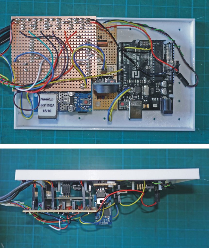
The picture above top shows the Veroboard almost covering the master Uno / Ethernet shield combination. The slave Uno is on the right. Between them are the RTC and the mosfet transistor. The picture below shows the edge view and you can see the DuPont connectors I have used to link the temperature sensors, servo etc. to the main board.
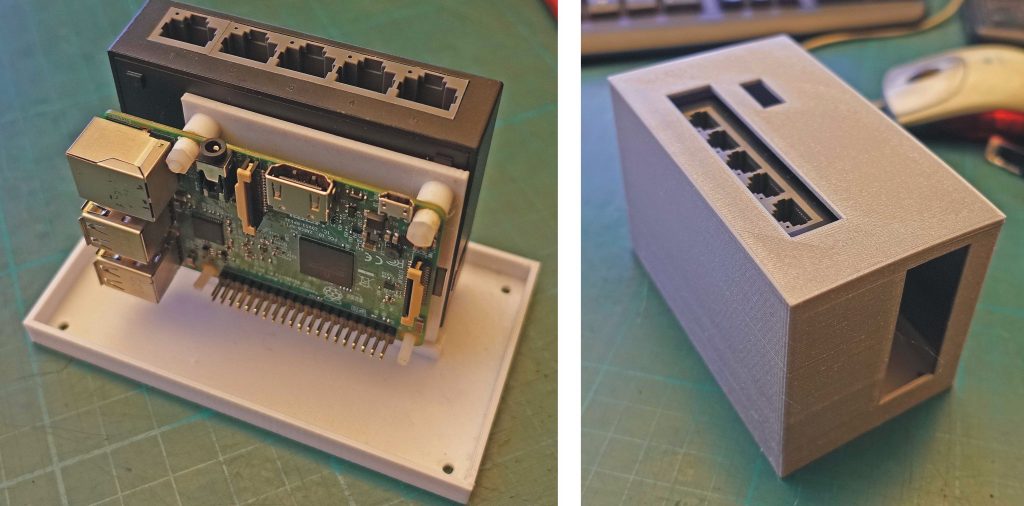
The picture above shows the Raspberry Pi controlling the Uno and the Ethernet switch which links everything together. The Pi which is a Mk 3 from an old discontinued project. Only very basic graphics required here so it is fine. Also shown is the 3D-printed case.
That’s all the construction, The rest, they say, is software!
Dashboard for boiler controller
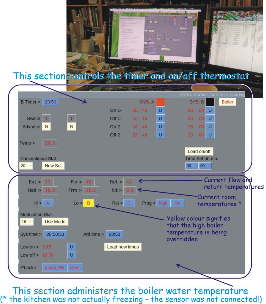
The picture above shows the current dashboard for controlling the boiler unit. The software is written in Python/TkInter and is running on a Raspberry Pi 4 being viewed on a PC using VNC (or on a tablet, phone etc. which can run VNC). It looks a bit retro (a charitable way of describing its appearance!) and reminds me very much of the software I was writing in the 1990s using Windows Visual Basic to read and write to the pins on the parallel printer port which used to be fitted to PCs which could turn things on and off etc. Maybe in the future I’ll tidy it up (or perhaps not!) For now it’s enough that it works.
The top section of the screen is very similar to my design for the boiler timer from several years ago. It allows times for the operation of the boiler for room heating and water heating to be set along with a thermostat setting. Also these settings can be advanced as required.
The bottom section is new for the boiler temperature controller. It allows the the time when the boiler runs at high and low temperature to be set. These can be manually overridden. A further system operates on top of this by default (but which can be disabled) to override settings and reduce the temperature when a set room temperature is exceeded. I think this sort of control may be more economical than the on off conventional thermostat as with the latter the heat input is at high boiler water temperature when on whereas in my system the boiler is running at a lower temperature which (as I understand it) is more efficient in a condensing boiler. (I could develop this argument more fully…) The system operates at full boiler temperature when the hot water system needs to heat up (otherwise the hot water would be lukewarm!)
See this page for details of the software.
Appendix
Substituting a Raspberry Pi Pico for the two Unos.
wondered whether a Pico could walk and chew gum at the same time (that is, read the OneWire sensors and operate the servo as a single Uno, by itself, didn’t seem able to do). A test program seemed to suggest it could. Given the cost of Unos or even clones this would represent a good cost saving. However, given my circumstances (Ethernet – yes : WiFi – no) is an Ethernet interface available. Apparently there is an Ethernet Hat for Pico but I haven’t been able to lay my hands on one yet. (I’ve got a Han Run HR911105A but I read this is not necessarily an ideal solution.)
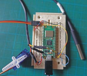
The test program is written in MicroPython. The servo is connected to GPIO pin1 and the OneWire to pin2. When the temperature crosses a threshold, the servo changes position.
# development of pico version of boiler control

import machine, onewire, ds18x20
from time import sleep
from machine import Pin, PWM
pwm1 = PWM(Pin(1))
pwm1.freq(50)

ds_pin = machine.Pin(2)

ds_sensor = ds18x20.DS18X20(onewire.OneWire(ds_pin))

roms = ds_sensor.scan()

print('Found DS devices')
print('Temperature (°C)')

while True:

  ds_sensor.convert_temp()

  sleep(1)

  for rom in roms:

    print(ds_sensor.read_temp(rom))
    if ds_sensor.read_temp(rom) > 20:
        pwm1.duty_u16(8000)

    elif ds_sensor.read_temp(rom) < 19:
        pwm1.duty_u16(1000)

  sleep(3)