Please reload Current Page on browser to ensure you have the latest updates!
See a video of my Laser Cutter here!
Introduction
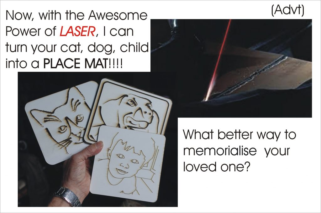
Having been impressed by the bond film, Goldfinger, many years ago I have decided to try to make a laser cutter. (Actually, I had access to a laser cutter some time ago and found it a very useful piece of kit. For example, I used it to cut the customised instrument panels for my TR7-V8 project.) Also, many years ago, I had been fascinated by home-made laser projects described in the The Amateur Scientist pages of the Scientific American (at the time, pre 2001, when it was a really good mag). Sadly, making a CO2 laser is probably beyond me now (it requires glass blowing, vacuum technology etc.) but I should be able to have a decent stab at a cutter if the numerous YouTube videos describing how it can be done are anything to go by.
Old Stuff…
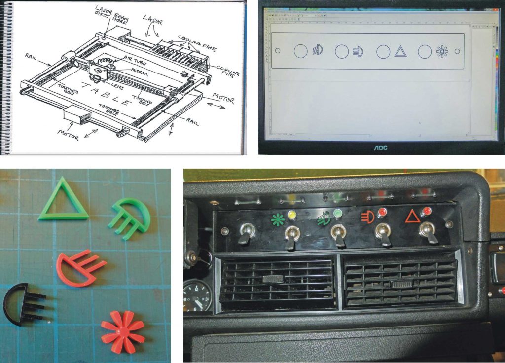
Below are some things I did when I had access to a laser cutter. It could cut 3mm Perspex and MDF easily but would not touch metal. Top left: The basic arrangement of a laser cutter with a stepper motor for each axis (X & Y). Top right: I designed the parts for the TR7 switch panel on CorelDraw. A printer driver for the laser cutter was loaded on my laptop and transferring the design to the cutter was as simple as any print job (getting designs into my laser cutter was to prove a little more involved but quite doable all the same). Below, middle left: The logos for the switches which were glued into the black panel with corresponding cut outs. Below, middle right: The panel installed in the car. Below, bottom left: Triumph logo for Nardi steering wheel. Below, bottom right: Illuminated TR7 V8 logo in panel on centre console. The logos were illuminated by LEDS glued to the back of the panel (I describe this in more detail on my old site, www.mr-r.co.uk).

Sections within this web page…
A sort of INDEX! Sorry, this is such a long web page! It’s divided into large number of sections (see below). I have written the page as I worked on the project over 15 months or so, like a blog. However, I’ve gone back and edited a few bits to make a bit more sense (hopefully!) You also have to be aware that I was designing this and, in many cases, discovering how to do things, as I went along. Perhaps I’ll rewrite the whole thing in a much more concise form in the future…
Initial construction, Making the gantry, Limit & interlock circuit, Setting up GRBL, Calibration, Testing by drawing, Trunking, Making the frame, Bed mechanism, Bed electronics, Mirrors, 3rd mirror & lens unit, Laser cradle, Initial laser test.
Making the base, Adjusting the laser cradle, Initial wiring & low voltage psu, Cooling system, Fitting up Raspberry Pi, Making the control panel, Further laser testing, Revised laser firing system.
Testing with various materials, Fume extraction, Making the case pt1, Engraving and more cutting, Making the case pt2, Tracing jpegs, Dragon project pt1, Case completion Laser current plots.
More dragons & other projects, box, moire effect cuts.
So, New Laser Cutter Project…
It strikes me that a laser cutter is in some ways easy to build, compared to, say, a CNC milling machine which has to have enough strength to press a rotating cutting tool against a piece of work and also move a heavy motor around in three dimensions. The laser cutter just needs to move some mirrors and a lens around in two dimensions. Hence the motion can be controlled by a toothed belt rather than a lead screw and nut. There is, of course the difficulty of lining up and focussing an invisible beam of light with the potential to blind or start a fire!
As far as I can see, all CO2 laser cutters are XY, Cartesian coordinate type machines. Not being averse to a left field solution, what other configurations are there that will be able to cover every point on a rectangular area? For example, something like the human arm pivoting at the shoulder and elbow would be possible. The business end is only supported by the levers and the two pivots which would have to be very rigid and free from play. Also I’m not sure how the laser mirrors would be arranged. Another configuration could be the delta arrangement used on some 3D printers. I’m not sure how the mirrors could work with this either. (However, these configurations would work, I would imagine, with laser diode engravers.) So, for a CO2 laser, Cartesian X-Y it is!
I’m going to have a good go at making as much of it as possible myself from basic parts. As I mentioned above, it would be nice to make the laser tube itself but that’s not going to happen! I’ll also give making the high voltage power supply a miss but that still leaves plenty to do!
Construction – thoughts & ideas
It would seem that by far the most popular way of making a laser cutter or similar is to make use of aluminium extrusions developed by OpenBuilds which feature V-edged grooves which can guide sliding carriages running on specially profiled wheels. These extrusions come in various different multiples of a basic 20x20mm base configuration. I have chosen 20x40mm versions as the carriages will run on the 40mm side providing a more accurate location than a 20x20mm extrusion. They will also be more rigid.
Mechanical Drive
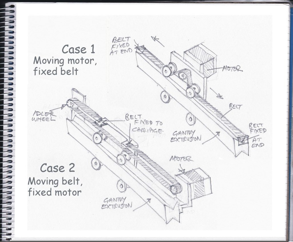
There seem to be two ways to cause a stepper motor to drive a carriage across an extrusion (see above). One way is to mount the stepper motor at the end of the extrusion and have a loop of drive belt the lenth of the extrusion with an idler wheel at the opposite end to the motor. The carriage is fixed to the belt at one point and is pulled back and forth as the bet moves. The other method places the motor on the carriage with a fixed belt which acts as a sort of rack to the drive wheel on the motor’s pinion. The belt passes under the wheels of the carriage and up (or possibly down) round the drive wheel on the motor making sure that sufficient teeth are in contact to ensure a secure drive. Which is better? (Answers on a postcard… As it turned out, I used both methods.)
Stepper Motors
The principle behind a stepper motor is quite simple; some electromagnets are turned on and off so as to drag magnets round and round. (I made a YouTube video which demonstrates this simple principle.) However, the details of driving the coils of the electromagnets at speed is a different matter and the theory of driving quite high current pulses into inductances might have been accessible to me when I was at college many years ago but now… not so much!
Fractional steps
More complexity involves fractional steps, when the magnets are not just dragged round to be exactly opposite one pole but are somewhere in between two. There may be up to 32 fractional steps. A half step is easy, adjacent poles are turned on so the magnet hovers halfway in between but 1/32 from one pole and 31/32 from the next must be tricky for the electronics driving the coils! Fortunately, clever ICs have been developed and Pololu (who seem to have a big share of the market) have incorporated them onto small breakout boards which can easily be incorporated into other circuitry.
Choosing the right Stepper Motor
I’m not sure how to choose the right stepper motors. The loads are light, so nothing very large should be necessary. NEMA 17 seems to be appropriate. The 17 in NEMA 17 – (National Electrical Manufacturers Association), just seems to refer to the diagonal distance between the fixing holes, in this case 1.7 inches. I am using Motech Motor type MT-1704HSM168A supplied by Ooznest. These are 0.9 degree per step motors (400 steps / revolution). Most seem to be 1.8 degrees (200 steps). The more steps, the better the resolution but, perhaps, the slower the speed? Time will tell whether I have made the right choice!
Electronics and Software etc.
2D and 3D CAD programs (my laser cutter will only need 2D design) will output vector graphics designs as files in svg or dxf format. These will have to be converted to a G-code file which contains instructions for the movement of stepper motors etc. tailored to the CNC machine being used. The CNC machine needs its own computer with software which can read the G-code instructions and send the required pulses to the stepper motor driver circuits.
Arduino Uno provides the Brains
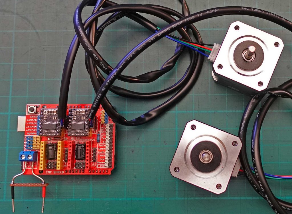
At this stage, this is how I see the electronics and software for this project developing. I am going down the open source route. I intend to use an Arduino Uno flashed with GRBL motion control software which can be customised with settings for individual machines. An Arduino CNC Shield will sit on the Uno and provide sockets for the Pololu stepper drivers and various jumpers which can be used to customise the operation of the whole kit and caboodle (see picture above – the Uno is under the CNC shield).
Not so Banggood
As an aside, I really feel for the guy who originated the CNC Shield. This is a quote from his site: “Due to Chinese Clones being sold for less than $5 and pricing me completely out of the market (and them not contributing to the project) I have decided to not publish future versions (of) design files.” And its true, on sites like Banggood you can find shields with clones of the Pololu drivers for peanuts. Apart from a lack of manufacturer’s logo, they look absolutely identical.
Of course, this is everywhere. Arduinos and similar have been cloned for years. I once bought a cloned Ethernet Shield, it was about £10 cheaper than a genuine item and I have felt (a bit) guilty ever since. This is, perhaps, the one area, the stealing of intellectual property, where I have a bit of sympathy for Trump. Did I just write that? UGH!
Add in a Raspberry Pi
I hope use a Raspberry Pi to send G-code to the Uno via a USB/serial connection. The Pi will run bCNC “Swiss army knife for all your CNC/g-code needs”. (Universal Gcode Sender is, I believe, an alternative.) Also, keeping things Pi-based, I could use Inkscape running on the Pi to do the required CAD work (but it’s probably going to struggle) or I could send files to the Pi from my PC over SSH etc. If required, I can monitor/control the Pi remotely from my PC using VNC.
Testing GRBL , the CNC Shield & Drivers

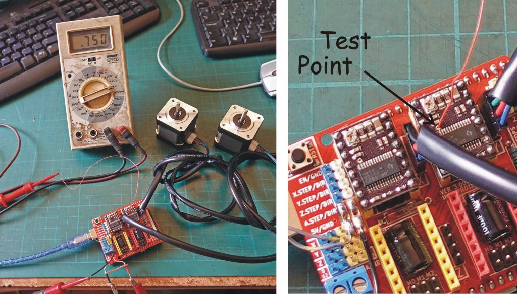
While waiting for some parts to arrive, I started to load some software. Flashing GRBL to the Arduino proved to be straightforward following these instructions and I was able to issue some G-code instructions (for example: G0 X100 or G1 Y-50 F100) using the Arduino IDE Serial Monitor (set the baud rate to 115200 or it won’t work!) and see a stepper motor run. The “running” did not seem totally right – sometimes it would seem to stop before it’s allotted number of steps had been run. Then I guessed that the DRV8825 might be overheating and shutting down while it cooled off. (As a person who had to use a pair of pliers to conduct the heat away for the leads of germanium transistors while soldering to prevent them being permanently cooked, I still can’t quite believe semiconductors can get so hot and still work!)
The problem was, I believe, A failure on my part to set the current limit. The easiest way to do this is to measure the voltage at a through hole connection on the Pololu PCB. I put a piece of 30 gauge wire through the hole to make contact and measure between this and ground. Twiddle the preset potentiometer on the board until the numerical value of the voltage is half the numerical value of the desired current limit (see picture below).
More Software
Next, I installed bCNC on the Raspberry Pi 4. This is a Python package utilising Tkinter. Installing a Python package is not completely straightforward for those who just dabble in Python like me! There are details here. According to someone on a blog (I can’t remember the reference!) you need the following installed first before installing bCNC: pip, numpy, scipy, tk, wheel, serial, setuptools PIL, and opencv. The last two allow X-Y alignment using a USB web-cam on the gantry. I’m not sure if this will be useful for laser cutting. Anyway, with some difficulty, I installed opencv using the instructions on this page. This also showed me how to install all these bits and pieces within a virtual environment which seems to be a good thing.
The otherwise perfect description of the opencv installation process seems to leave out a couple of points. Under “Step #4”, add the following lines to your ~/.profile:
export WORKON_HOME=$HOME/.virtualenvs
export VIRTUALENVWRAPPER_PYTHON=/usr/bin/python3
export VIRTUALENVWRAPPER_VIRTUALENV=/usr/local/bin/virtualenv
source /usr/local/bin/virtualenvwrapper.sh
export VIRTUALENVWRAPPER_ENV_BIN_DIR=bin
Without the last line, I got the error /home/pi/.virtualenvs/cv does not contain an activate script. Also, to ensure that the virtual environmet works when you close the original shell and open another, you have to add these lines to ~/.bashrc:
export WORKON_HOME=~/.virtualenvs
VIRTUALENVWRAPPER_PYTHON='/usr/bin/python3'
source /usr/local/bin/virtualenvwrapper.sh
Then you have to source ~/.bashrc to activale the changes.
Initial testing of bCNC
So having finally got bCNC installed on a Rpi, I connected the Arduino/CNC Shield with a USB lead and started bCNC (open a terminal window and enter workon cv – cv being the name of my virtual environment – then enter bCNC return).. I selected the correct port by trial and error (it was /dev/tty/ACM0) and was able to run both the X and Y axis motors by clicking on the “Move Gantry” button, moving the cursor on the drawing board (is that what it’s called?) and clicking.
Construction begins!
Some parts arrived from Ooznest, so I was able to start construction. For now, I am concentrating on building a two-axis, CNC-controlled (in effect) plotter. If I can get that working, I will then invest in a 60 Watt CO2 laser.
V-slot makes it easy
The use of Openbuilds type parts seems to be universal for self-build projects and that is the route I am taking. I have bought enough 20/40mm V-slot extrusion to make a rectangular frame and a gantry to move up and down it. As I mentioned above, 20/40 seems to be the right dimension of extrusion for a machine in the region of 900 x 500 mm. I relied on Ooznest to cut the extrusions to length. It’s really important they are cut really accurately and exactly square and they have the right saw to do it. I have seen videos of mitre saws being used and it is true that almost any type of blade can cut aluminium (without, in my experience, getting rapidly blunted – as a child, I used woodworking brace and bit augers to cut holes in aluminium to mount valve or vacuum tube bases and they are still fine after fifty odd years with only the occasional sharpening). However, most setups will not be as accurate as is required in my view.
Bits & bobs
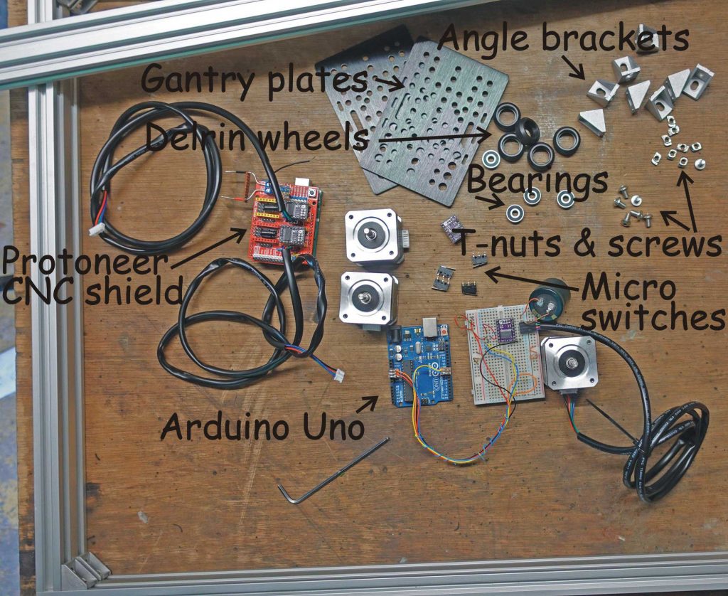
I bought a job lot of angle brackets, a bag of 5mm T-slot nuts and 8mm button-head stainless steel socket-head screws from Ebay and Amazon and assembled a frame. I had never used T-slot extrusions before but I was impressed with how quickly it all goes together. Put the screw through the bracket, start the nut on the screw, push it through the slot, turn the screw with a ball-headed Allen key and the nut spins round and jams at ninety degrees before it finally tightens up. Voila! Job done!
Having, therefore, got a frame and a bar which would act as the Y gantry, I purchased three V-slot gantry plates (with Delrin wheels which slide along the V-slot), some 2GT Gates Open Timing Belt (6mm wide) three 2GT Pulleys – 30 Tooth (for 6mm belt – 5mm bore to fit the steppers) and a couple of 2GT 20 – toothed Idlers – again from Ooznest.
Then I needed to make up a lot of brackets and similar bits and bobs to hold the stepper motors, tension the drive belts and attach limit switches etc. I made these mostly out of 3mm (or 3.2mm) aluminium plate or angle.
Accurate drilling (hopefully!)
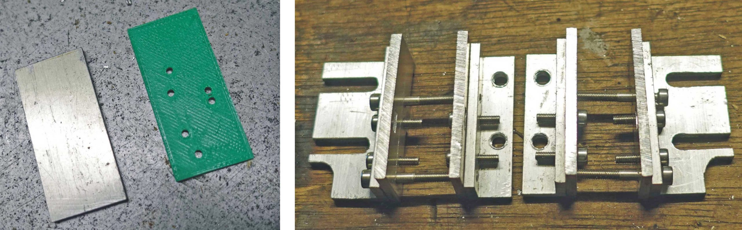
In order to accurately place holes and in the absence of a CNC drill/mill (perhaps this is what I should be making?) I used my 3D printer to make patterns with the holes in the right places. The patterns had 2mm holes for pilot drills which were then enlarged. The problem with this method is that the patterns only last one time as the holes in the PLA are quickly enlarged.
Fortunately, the accuracy of operation of the finished machine depends on the accuracy of the stepper motors and the Grbl software driving them (and the belts and pulleys, perhaps). For the most part, a lack of accuracy in the construction of a few tenths of a millimetre on my part will not be a problem.
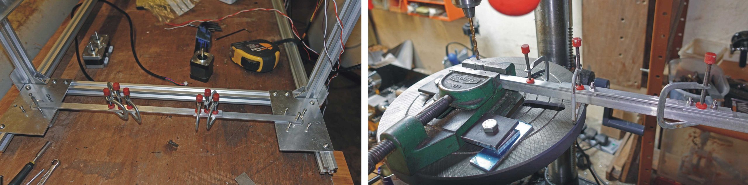
When enlarging the pilot holes, it pays to clamp the work down to the drill table as just holding it “loose” with a machine vice inevitably leads the hole to wander out of true. This problem increases as the diameter of the hole increases – for example, the hole for the location of the stepper motor (22mm diameter) for which I used a stepped drill (from Aldi!). I scribe a 22mm diameter circle with dividers first so that I am reasonably confident the hole is in the right place as the hole increases in size.
Below, left: A 3D printed drilling pattern. Below, right: Belt tensioner for the Y gantry (still needs a bit of finishing!)
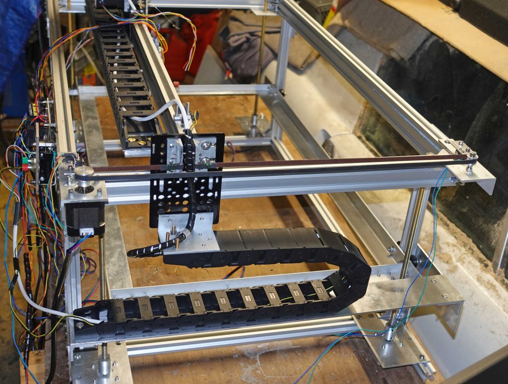
Below, left: The Y axis tensioner – the screws marked by the arrows adjust the tesion with clamping screws on the slots. Below, right: The X axis version.
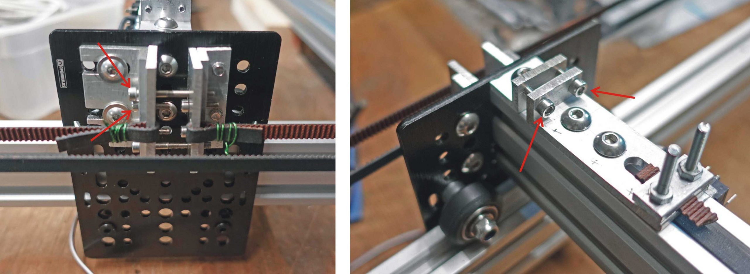
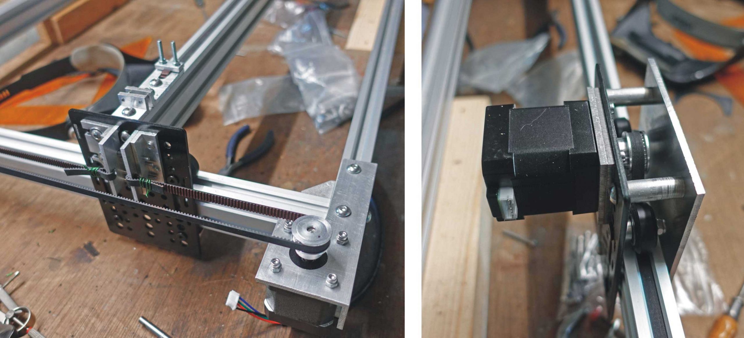
Below, left: The Y drive arrangement. Below, right: The X drive arrangement. Here I’ve had to space the motor out from the gantry plate with two thicknesses of 3.2 mm aluminium plate to get the drive pulley over the centre of the slot. As you can see, I’ve used both the drive arrangements described at the beginning of this page.
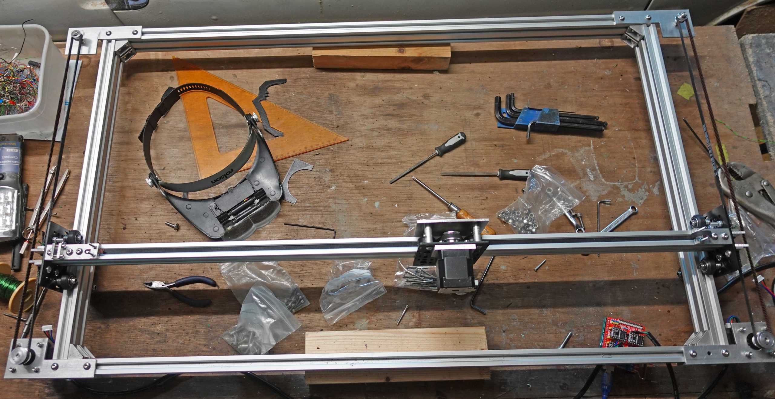
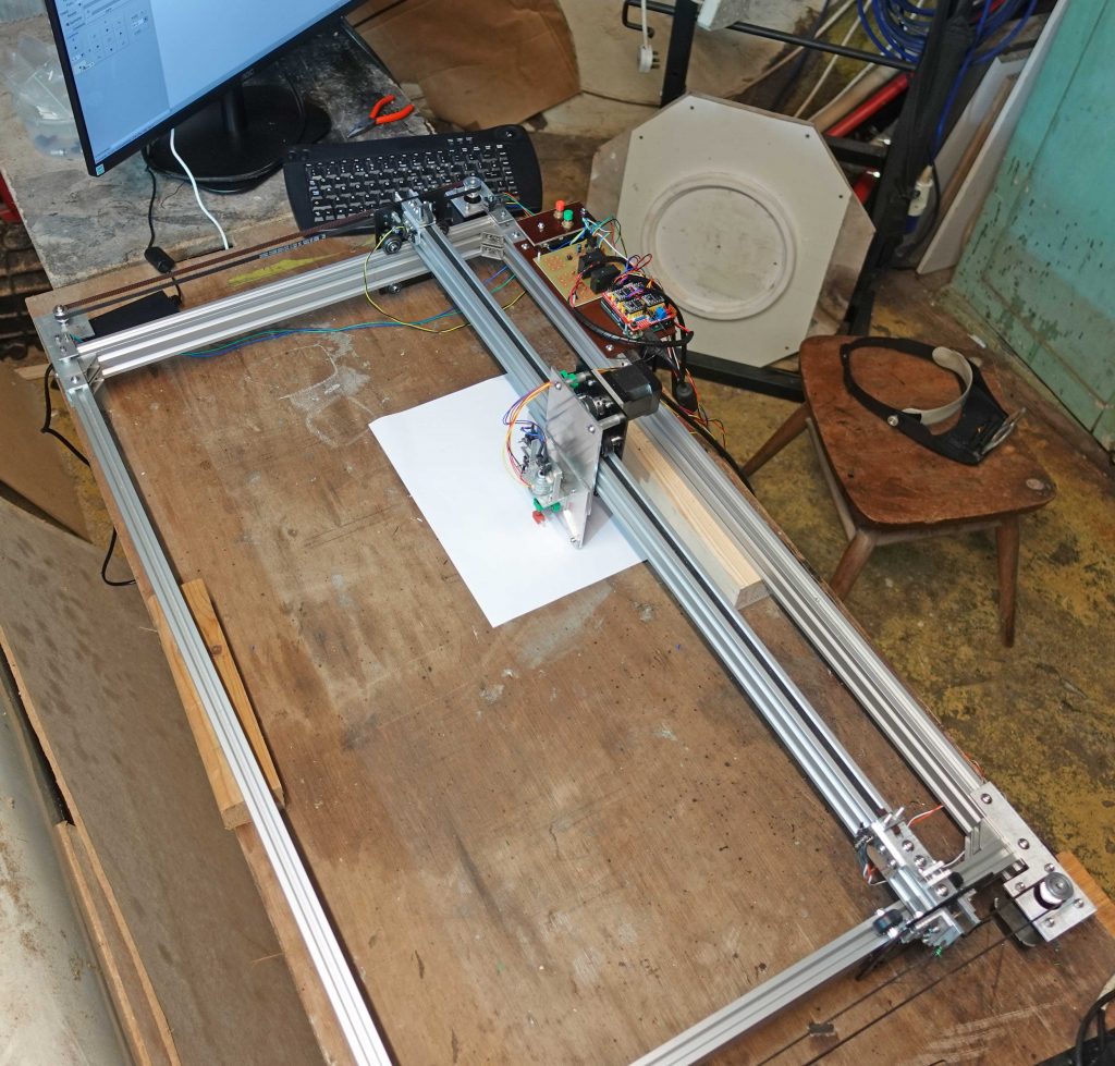
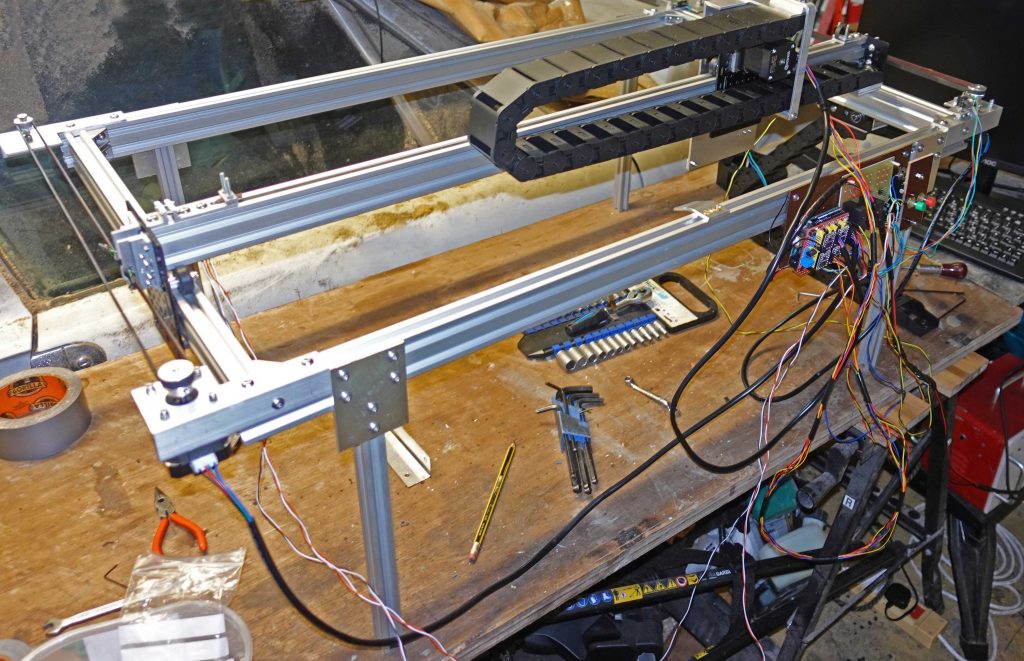
Below: The basic arrangement completed (sort of!) For the time being it’s just resting on blocks of wood.
Limit switches
In addition to the X and Y limit switches at bottom left which will be connected to the CNC Shield to establish the home position, I fitted four other switches to detect out of range movement of the gantry; two each at max. and min. X and Y movement. (For the moment, I am not considering any possible Z movement – at this stage I don’t know how this will work out.)
Safety limit switch circuit
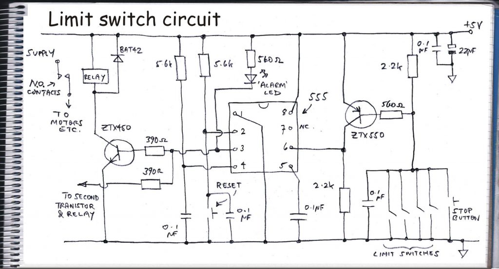
I am connecting these four limit switches to an independent circuit which will cut out power to the stepper motors (and the laser). (I am aware grbl could do this but I want the extra safety of being grbl-independent.) The circuit is a bi-stable latch arrangement using my old friend the 555 IC (see above drawing). This will switch a couple of relays (Panasonic ALE1PB05, 277VAC, 30VDC, 16A, 5V coil from Farnell, 1712521) which will control power to the steppers and laser as just mentioned. On the 555, taking pin 2 low switches the output high and taking pin 6 high switches the output low. The 555 output drives the relays via a couple of transistors to provide the current. Pin 6 is connected to an inverting transistor so that taking the base connection of the transistor low will take pin 6 high. This enables the limit switches to short to ground rather than 5 volts. (This seemed like a good idea but I can’t exactly say why!)
PCB layout
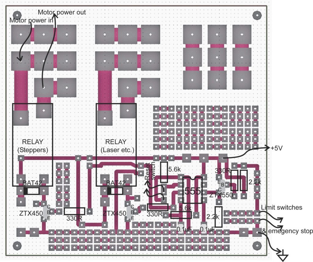
As usual the pcb provides plenty of “prototyping” pads for components I have forgotten to include at the design stage. The pcb layout does not show the 0.1uF capacitors across the limit switches and reset switch as I incorporated these after I had designed the pcb and they had to be soldered on the track side (I found the inputs could be triggered by just touching them with something metallic which isn’t good!) The layout also doesn’t show the LED which lights on power up and when the limits are triggered. Also the 22uF and 0.1uF bypass capacitors are not shown. Also there are some minor changes to resistor values which reflect what came to hand (resistor values are mostly non-critical – except when they are!)
Power supplies
The 5 volts comes from the Raspberry Pi via the USB lead. I worry that switching pulses for the relays will feed back into the Pi and the Arduino and upset things but so far, this has not happened. (Incidentally, the power for the three stepper motors is coming from a 15 volt power supply I made many years ago. It has a large mains transformer and a hefty smoothing capacitor. I understand this is desirable to smooth out high transient currents derived from pulsing the steppers. I will construct a new power supply in the fullness of time – probably!)
Safe at start up
The 555 has its reset pin (4) taken to 5 volts via a resistor and to ground via a 0.1 uF capacitor. This ensures that on power up, the 555 is in a reset state i.e. the output (pin 3) is low. That means that on power up the supplies to the motors and laser are disconnected. The power is enabled by taking pin 2 low with a push button switch. (So the machine does not start up if mains power, say, is unexpectedly applied.)
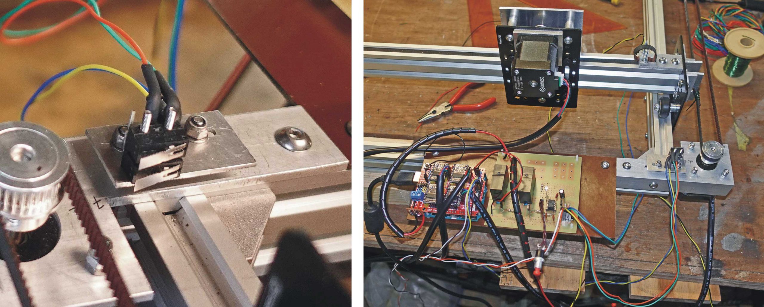
Above, left: This shows the limit switches for min. Y. The bottom switch is to establish the Y home position, the top switch works with circuit described above. The picture above, right shows the CNC shield (with the Arduino Uno underneath) and the safety limit circuit with its two relays, 555 etc. plus a whole mess of wires which will (hopefully) be tidied up as the project progresses. For convenience the electronics are screwed to a piece of Tufnol attached to the V-slot. They will probably be repositioned as the project progresses.
By pure luck, the safety limit switches trigger a fraction after the homing limit switches (probably because of slight variations in the bend of the lever) which means that homing does not trigger the safety cut out. If this had not been the case, I would have had to kept the reset button pressed during homing (the red reset button can be seen hanging from the circuit in a temporary configuration).
Edit config.h
Before I could do any testing, I had to get the machine to “home” on just the x and y axes. You have to edit the config.h file in the Grbl distribution, the recompile Grbl on your Arduino Uno. Probably a good idea save the original config.h to a location where it can’t be found during the compilation process otherwise you will get errors.
Comment out the line:
#define HOMING_CYCLE_0 (1<<Z_AXIS) // REQUIRED: First move Z to clear workspace.
Then uncomment lines:
#define HOMING_CYCLE_0 (1<<X_AXIS) // COREXY COMPATIBLE: First home X
#define HOMING_CYCLE_1 (1<<Y_AXIS) // COREXY COMPATIBLE: Then home Y
During recompilation, I noticed that various Grbl settings were retained. I assume these are not overwritten with the generic values when Grbl is recompiled if changes are detected? Perhaps theses are stored in EEPROM memory, if you want to really start from scratch, this should be erased first. See https://www.arduino.cc/en/Tutorial/EEPROMClear.
(I later noticed this was a feature (with a number of options) which can be adjusted in the config.h file. No need to clear EEPROM “manually”! There a numerous other features which I will have to come to grips with later on!)
Initial testing
Having done this, I started bCNC on the Raspberry Pi and connected to the Arduino by clicking on the appropriate button. Initially, as a safety measure, the system starts in an alarm condition so the “unlock” button needs to be clicked on. Then I could click on “Home” and watch the gantry do its thing!
Next, I used the “jog” arrows to move the gantry beyond its limits to test the appropriate limit switches connected to my 555 circuit. The motors cut out as expected.
Calibration
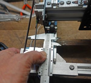
Then I was in a position to calibrate the X and Y movements in terms of steps per mm. Set the jog to move 10 mm and measure the actual movement with a vernier gauge (see picture above). Allow the carriage to push the vernier gauge then measure how much it has been moved. Calculate the revised number of steps and enter the value in the Grbl settings. New step value = old value * 10 / measured movement. I used the Serial Monitor facility on the Arduino IDE to input the values (set the baud rate to 115200 or it won’t work! $100 sets the X value, $101, the Y value.) Then test again. Repeat until the gantry moves as it should. Set the gantry to move 100 mm and test again, repeating until the movement is correct. I got very slightly different values for X and Y despite the fact the motors and drive pulleys are the same. Perhaps this is down to belt tension. I will (perhaps!) test this out in the future.
Testing by drawing
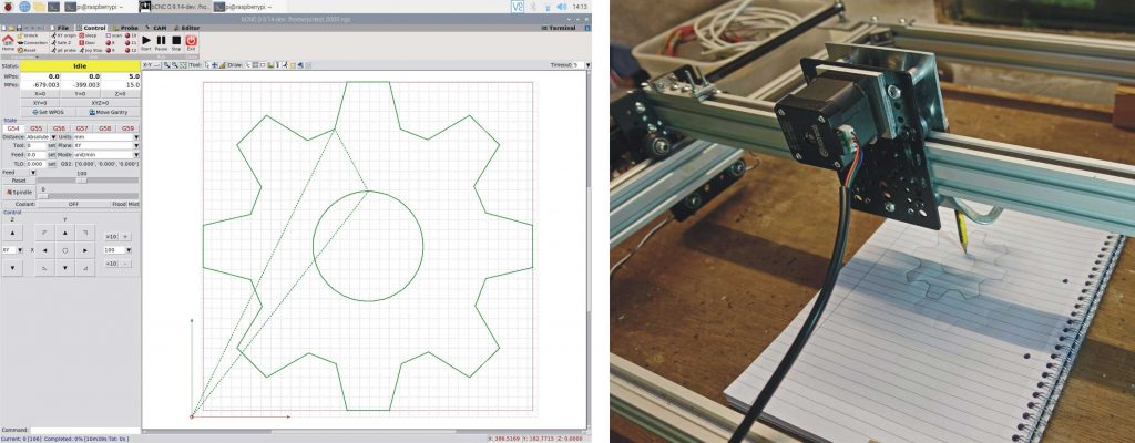
Next, I tried to determine whether the gantry would actually move according to some sort of GCODE file (the language of CNC machines). The free Illustrator – like program Inkscape can output 2D GCODE files and I used this with a drawing of a simple gear wheel. (I actually drew this on my ancient version of Corel Draw 9 with which I am very familiar – and, now, can be downloaded for free, by the way, although I can’t say if it’s been hobbled in any way – and exported/opened this as a .cdr file in Inkscape.)
There is some sort of bug in this process as the drawing appears smaller than it should. I understand this may be related to a confusion on the program’s part between pixels and points as unit of length. It appears that a scaling factor of 4/3 or 133.333% will bring it back to the correct size.
Rather than apply a scaling factor, the easiest way is to just set appropriate guides in Inkscape and stretch the CorelDraw derived drawing to fit.
In order to generate GCODE, I took the following steps. First, from the Layer menu, I added a layer, then, from the Path menu, I clicked on Object to Path. Finally in the Extensions menu I went to Gcodetools, Path to gcode. I accepted all the defaults and ignored all the warnings which produced an .ngc file which is a text file comprising GCODE commands. I then transferred the file to the Raspberry Pi using Win SCP.
(Later, I found that the LaserGRBL program is much better at creating GCODE than this Inkscape add-on – see later for more details.)
It draws!
I clamped a pencil to the gantry, loaded the file into bCNC and started it up. I was rewarded by a rather neat drawing of a cog! (Below, left: The cog on bCNC. Below, right: The machine drawing said cog.)
More calibration attempts
Finally, in this phase, I drew a 50 x 50 mm square in Inkscape, outputted the GCODE to bCNC and ran it on the machine. While it was running I nudged a vernier gauge in both the X and Y directions. I found an error of about 0.3 mm in the Y direction over this distance. This seemed to show that I had been wrong with my initial calibration when I seemed to detect the need for very slightly different values in steps/mm for X and Y. I fiddled around with the values for $100 and $101 to improve matters. The current provisional value is 107.2 steps / mm for both X and Y.
Better drawing
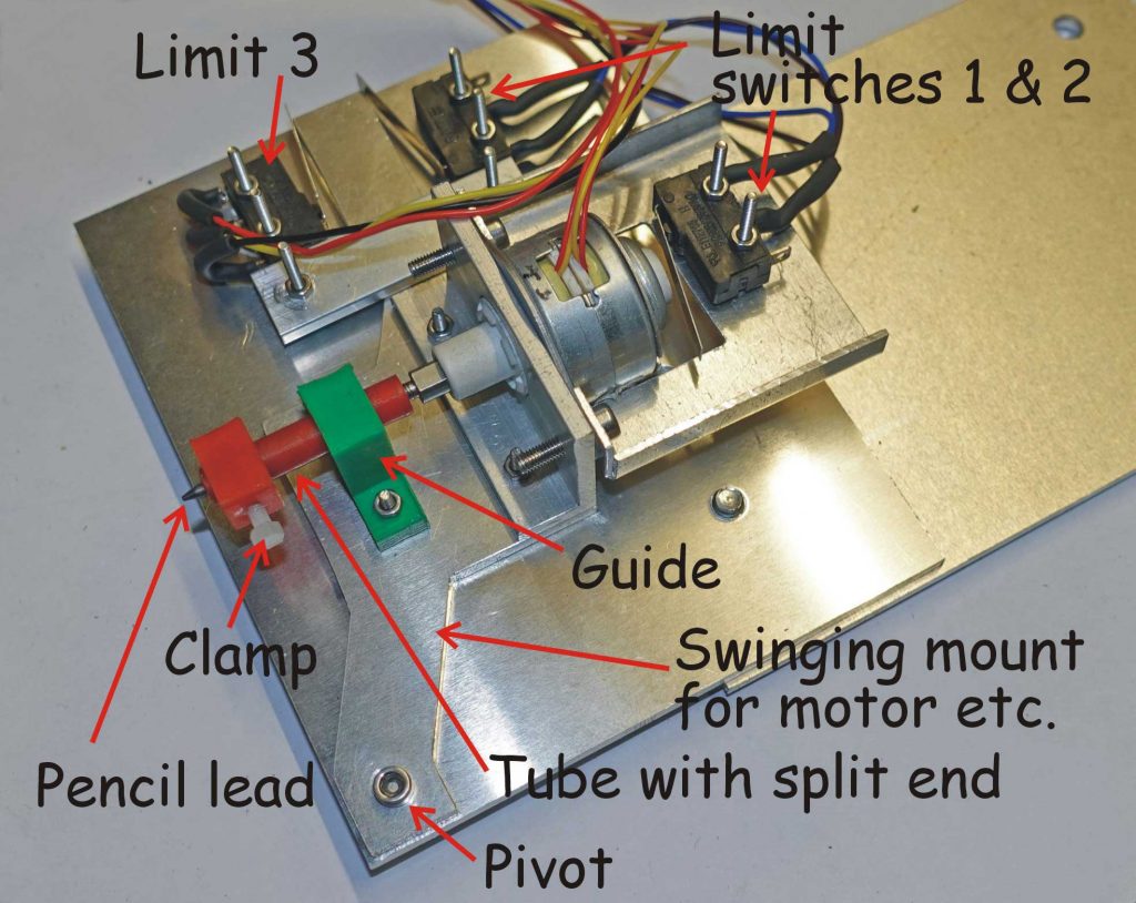
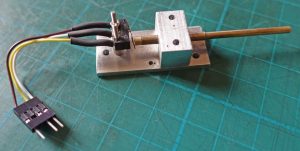
Next I made a stepper motor – enabled “drawing head” to test my abilities to control the Z-axis (see picture below). The motor, which is fitted with a lead screw to provide linear motion, lifts a pencil lead up and down. The motor pivots so that the pressure on the lead on the paper is governed by the weight of the motor. (Later, I added a weak spring to increase this pressure.) The motor sends the pencil lead down till it hits the paper. Once that happens, it swings on the pivot on the pivot until a microswitch is triggered which sets the home position. That’s the theory, anyway!
First, I had to recompile Grbl with the Z axis homing included in config.h. Then I adjusted the Z axis maximum rate to 50mm / min ($112) – although, later I found that 500mm / minute worked fine!.
I had bought the stepper motor years ago in connection with a project to control engine idle speed automatically and I had no idea of its spec. I figured that any motor is capable of half steps so I set the jumpers on the Pololu board to that. It sounds a bit rattly but works ok.
With that done I tested the Z setup by jogging and roughly calibrated the movement of the lead screw. ($102 = 25). I had a lot of trouble trying to get the Z axis to home and went down all sorts of rabbit holes until I discovered that as of grbl 0.9, the Z limit signal pin (D11 on the Arduino) has been swapped with spin-enable (D12) so that’s where the switch should be plugged!
Real-time (?)
While trying to get the Z axis to work, I tried to get real-time status reports which might inform me about the limit switch positions (? in grbl). This involves setting $10 which is a 5-bit mask (I think!). A value of 1 signifies machine position: a 2, work position: 4, planner buffer (?): 8, RX buffer (?): 16, limit pins. It seems that bCNC depends on the machine position report in some way and if the 1 position is not set, it goes a bit haywire and claims bCNC is not connected though it is, as you can jog and, as far as I can remember, still home. So any number you set for $10 must be odd!
Home again
My aim at this stage was to home the pencil resting on the paper. How it gets lifted off during the execution of a GCODE file, I don’t know yet! At first I intended to use limit 3 to home the pencil. The idea was that the motor would start of with the pencil lifted off the paper so that switch 3 would be closed (the NC contacts, though, would be open). As the motor caused the pencil to hit the paper, the switch would open and the NC contacts would close. This did not work, however, I think, because there is not enough space for the limit switch pull off routine to work as it should. (By good fortune, however, I found later that I could put switch 3 to good use after all – see below.)
I reverted to limits 1 and 2 (connected in parallel). This worked once I had allowed enough maximum travel on the Z axis ($132 = 20). I connected the motor to move up on homing so the top microswitch registers that position with the pencil lead clear of the paper.
Probing
To get the pencil lead in contact with the paper, I need to use the Probe facility. This needs a switch or contact between the Arduino A5/SCL pin and ground (this will have been setup by Grbl as a digital input pin, I presume). Having connected switch 3 to do this, I started by jogging down in steps of 0.1mm. When the tip hits the paper, the swinging arm moves until a point is reached when limit three is released and the NC contact closes. This is registered on bCNC by the status readout Idle (P) on completion of the jog, signifying that the probe has been triggered.
Gcode
The Gcode G38.2 probes towards the workpiece, stops on contact and signals an error on failure. So the command: G38.2 Z-1 F1 sends the pencil down to the paper. When I tested this, Z went from -19 (home – I assume 19 is related to the 20 maximum allowed movement I have set in Grbl for Z) to -6.84 which reflects the dimensions of the Z components of the machine, distance from the bed, thickness of the paper etc. A command such as: G1 Z-16 F1 moves the pencil to coordinate -16 which is clear of the paper. There is a place in Inkscape / Extensions / Path to Gcode which allows a safe distance to be entered.
bCNC buttons
(I wanted to build these commands into two of the user-configurable buttons on bCNC. I was able to do this but, so far, I have been unable to save them – the heading Buttons in the .bCNC file located in /home/pi, remains blank.)
Drawing
This is the procedure for drawing a file/picture:
- Home the machine
- Set the work position to the machine position (-19.0 in this case)
- Put the pencil down to the probe contact position
- Jog +Z 3mm to clear the probe contact microswitch (allows the pencil to keep contact with the paper better)
- Zero the work position
- Run the file
The Gcode I have produced runs the paths twice. I need to understand how to stop this happening. (I could just edit out the second runs in the Gcode file but that would be cheating?)
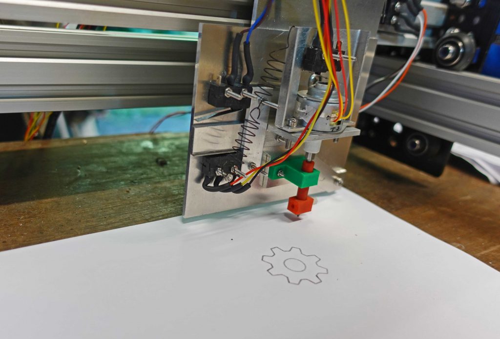
The picture above shows another instance of the picture of the gear, this time made with the stepper motor-equipped drawing head. You can see the spring (actually two hooked together) which I fitted to increase the pressure of the pencil on the paper.
Cables under control
Cable trunking was now on the agenda. I didn’t know quite what size to pick, so I chose 18 x 37 which when I actually got it looked rather large. Still better too large than too small as long as the stepper motors can haul it along!
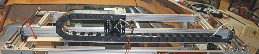
I tried the trunking in various positions, pivoting in the horizontal and the vertical planes. In the end it seemed there was no alternative to the position shown in the picture above.
In order to support the trunking, I tried attaching a roller support hung off the gantry plate which held up the trunking as the gantry plate moved along. However, a neater solution was to fit a plate the length of the gantry plate (see arrow on the picture above) supported off the gantry at either end so that the movement of the gantry plate was not impeded. The trunking connecting to the gantry similarly will be supported by a plate which will be attached to the machine’s frame.
Now I need to repeat the exercise on the right hand side of the frame, probably underneath the drive belt. This will mean raising up the machine with the next stage of the construction… Then I will have to redo a fair number of the cables as they are too short at present!
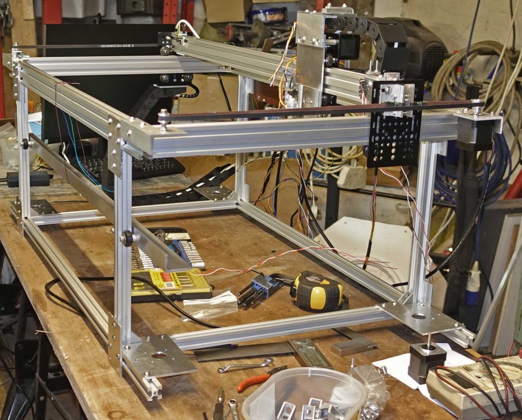
Raise up the frame!
The machine goes up in the world with four legs 300mm long (see picture above – the 20×20 extrusion looks a bit spindly but, hopefully, it will be all right). There will be a bottom frame under these legs, probably 1000 x 540mm. (Remember I’m designing this as I go along!)
(NB. The picture above doesn’t show the support plate for the trunking.)
Making it up as I go along (the bed – that is)!
Inside this skeleton box will sit the bed (aluminium honeycomb or, perhaps, ni-chrome, or similar, wire mesh) which will be raised and lowered by four stepper motors fitted with 8mm lead screws. I’m thinking it would be easier to use four motors rather than one with belt drive, bearings etc. etc. However I will need four Pololu drivers and a perhaps a CNC shield but driven by an Arduino running basic software (not Grbl). I envisage pressing a button, the bed descends to its home position, then rises till the work on the bed encounters a probe on the laser head, plus controls to manually raise and lower. The question remains as to whether I shall need guide rods with linear bearings etc. in addition to the lead screws (which will have some sort of top bearing). Obviously, I don’t want the bed to wobble when the laser is doing its work!
I envisage all this being inside a sealed box with the usual hinged lid for access all sitting on a table under which would be all the other gubbins needed (extractor, air pump, chiller, power supplies etc.)
Back to bed
Back to raising and lowering the bed, I thought long and hard about how to design in an accurate vertical motion. One of the problems, it seems to me, is ensuring that the bed can move smoothly up and down without significant slackness from side to side requiring linear bearings of some sort with very little play. This requires quite accurate construction of the framing etc. to which these bearings are attached. Although the position of bearings etc. can be made adjustable, the squareness of a frame can be tricky to achieve and needs a lot of fiddling with try-squares etc.
Doesn’t fall flat – unfortunately
More difficult, I think, is making sure a large rectangular frame, say, is flat. You can build your structure on a piece of block-board or thick MDF which will be pretty flat but will flex a little if the table or trestles on which the surface is not flat and so on. I have a self-levelling optical level which I am going to use eventually when I am doing the final alignment. This should be able to measure “flatness” to a fraction of a mm. Hopefully it will be enough! Or, perhaps, the vertical dimension of a laser cutter is not that critical (relatively) compared to, say, a milling machine or 3D printer. Time will tell (again, you have to remember, I am making this up as I go along!)
I get a bit square
Anyway, I contented myself at this point, by getting the frame as square as possible. First, it is a good start to have all the frame members the right length. This is where having the supplier cut the pieces with their expensive special saws pays dividends! Getting the frame square involves loosening joints and sliding them here and there and checking measurements with a tape, vernier gauge etc. as appropriate.
Bed mechanism
I toyed with the idea of raising the bed on three screws as opposed to four. Three would be (obviously) cheaper and less likely to jam if things got out of hand (a three-legged stool never wobbles etc.) In the end, I went down the conventional route (four) which better supports the bed.
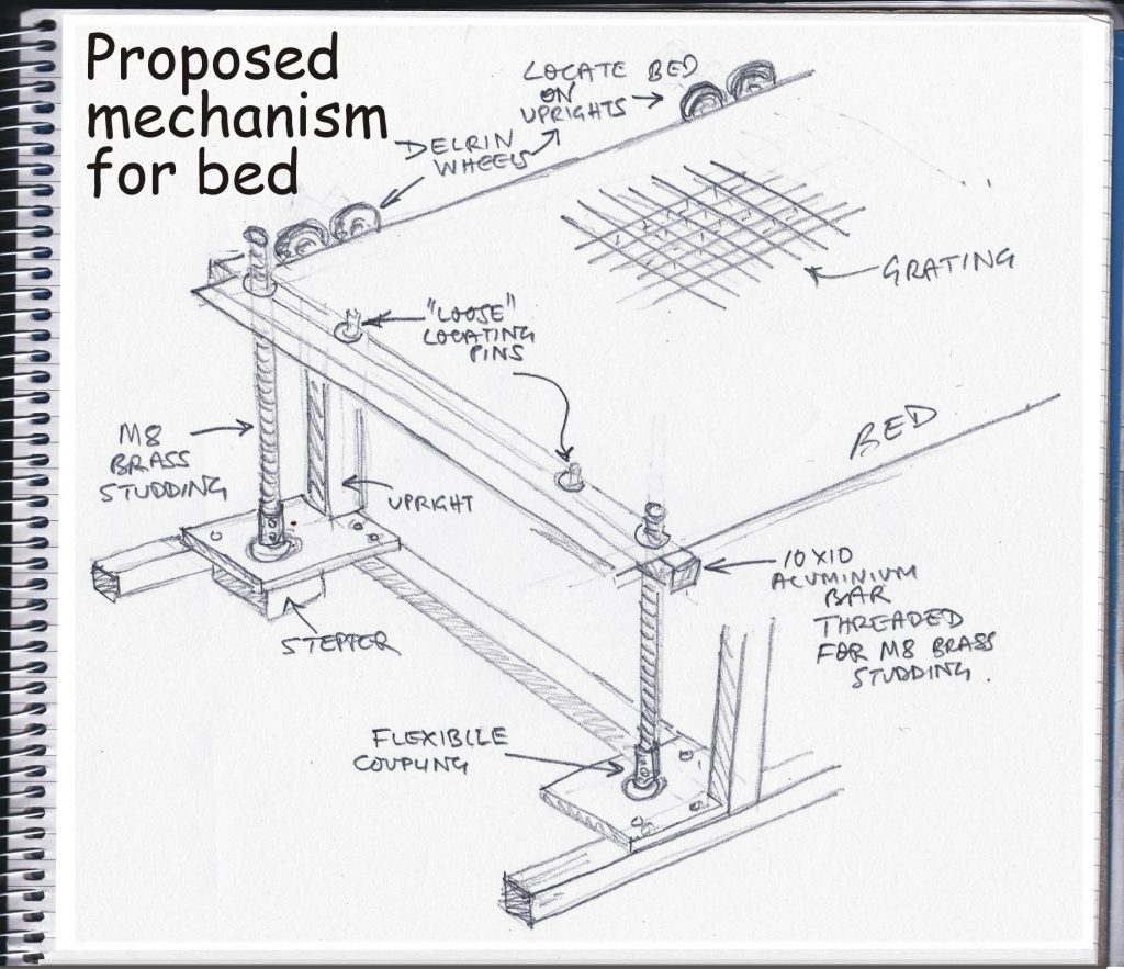
I looked at stepper motors directly connected to Acme lead screws and nuts and the prices from Banggood seemed attractive. However the chances of receiving them without any bends caused by poor transit arrangements militated against this choice. In the end I opted for four cheap stepper motors from Ebay (they don’t have to be very powerful, fast, high resolution etc. I hope). I am coupling this up with lead screws made from M8 brass studding (easy to cut and machine and needs a minimum of lubrication).
Motor mounting plates
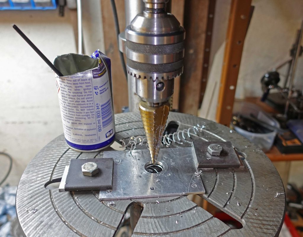
The first thing to do is make the mounting plates for the four stepper motors. It’s quite important here to drill the holes for the motor in the right place for the motor to fit and also correct relative to the edges of the plate. I 3D-printed another pattern/template which I used to drill 2.5mm pilot holes in the first plate. I used this plate as a pattern for the other three plates. I then enlarged the holes as required. For the 22 mm stepper motor location hole I used my stepper drill (from Aldi!). This produces a round hole in thin material (thin relative to the diameter of the hole), whereas a conventional twist drill may leave a hexagonal hole (in thin material).
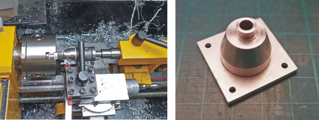
Location, location…
I located the plate by drilling the first “step”, then clamped the plate on the drill press (as shown in the picture above) before running through the “steps” up to 22 mm. Lubrication with something like WD40 is necessary with all drilling in aluminium alloy. Nevertheless, there is always an annoying burr which I normally cut off with a wood working chisel.
Clamping when drilling a large hole is essential to ensure the hole is reasonably close to where you want it. Also clamping is a great for safety. If you are holding the work with your hand and the drill bitcatches the work will flail around with potentially serious consequences for your hand! Even a small piece of work can fail to break through cleanly and run up the drill bit at the very least messing up the hole, particularly in something soft like aluminium. On the other hand if you have many small holes to drill life is too short (perhaps) to clamp every one…
A little disappointment
Disappointingly, I had to enlarge the four 3 mm holes to get the stepper motors to fit. I suppose the 22 mm hole wandered up to 0.5 mm as I drilled it. This could be due to play in the drill press shaft. Probably a better way would have been to drill the 22 mm hole first, then use a 3D-printed pattern/jig with a flange which located into the hole and subsequently drill the four 3 mm holes using this pattern.
Progress on the bed
My next task was to fit the Delrin guide wheels on the rear member of the bed (see sketch above). I know that the centres for each pair of wheels need to be 40 mm apart (for a 20 mm extrusion). Not only do I need to be able to drill these holes accurately, I also need to space the pairs of wheels to match the dimensions of the frame.
First I rechecked the separation of the rear uprights top and bottom and made further slight adjustments to get them as square as possible. Then I marked the positions of the uprights on the angle which will become the aforementioned rear member of the frame. I then set out the positions of the holes for the guide wheels.
I expected that inaccuracies would creep in and that I would have to elongate some of the holes (or use the eccentric mounting bushes which I used on the gantry plates etc. In the event, I got lucky and the holes I drilled positioned the wheels accurately enough to allow the bed member to move up and down with pretty much zero detectable play.
Next were two 12 x 12 mm bars with M8 female threads at the separation of the stepper motors. To get as good a positioning for the holes as possible, I made a gauge consisting of three pieces of 12 x 3 mm bar, two with 5 mm holes to fit over the motor spindles and one to link them together. While fitted to the motor spindles, I clamped the third piece in place and then drilled holes to bolt the pieces together. Then I clamped the gauge onto the 12 x 12 bar and drilled 5 mm pilot holes which I enlarged to 6.5 mm ready for tapping out to M8 thread.
Above, left: The three pieces of 12 mm wide alloy fitted over the motor spindles and clamped together. Above, right: The parts of the gauge bolted together and clamped on the 12 x 12 bar ready for drilling.
Turn, turn, turn
The next task was to turn down one end of the four pieces of M8 brass studding (threaded rod) to 6 mm to fit a flexible coupling that I will be using to connect it to the stepper motor (picture below).
Bed setup
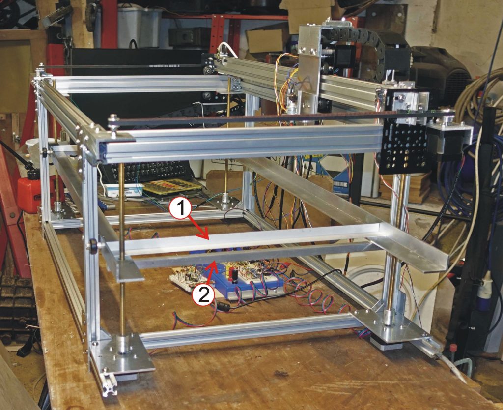
The picture above shows the four stepper motors and the lead screws temporarily in place screwed into the 12 x 12 mm support bar (2). Aluminium angle (2) rests in place temporarily. It will be bolted to the front and rear members to complete the frame which will support the aluminium honeycomb bed.
The pictures above show details of the lead screws. On the right, I have fitted a nyloc nut to the top of the lead screw to make it easier to manually adjust the corners of the the bed when getting it level, with the outer case in place.
On the grid
I’ve also made a grid from 10 x 3mm bar on edge to further support the aluminium honeycomb. The pictures below show how the bar is attached to the outer frame using pieces of 12 x 12mm bar notched to locate the ends of the bars. Top left: I used the band saw to cut the slots in the end of a long piece of 12×12 bar so that I could use the cross-cut guide, then cut the pieces off the bar to the correct length. I finished the slots off with a small file, which is, luckily, 3.2 mm (1/8 inch) at its thickest point, until the file just passed through the slot. Some WD40 on the file stops it sticking too much. These pieces were drilled to 2.5mm ready to be tapped to M3 so they can be screwed to the outer frame. The long bar and the two shorter cross bars are half jointed together.
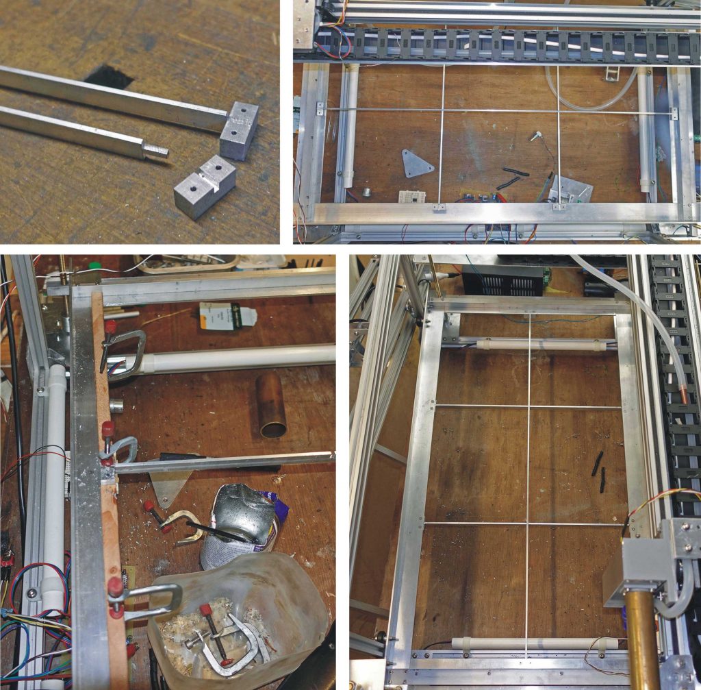
I assembled the grid on the top of the frame and cut pieces of wood to jam the parts in place (top right and bottom left, above). I used mini clamps the fix one side securely while I drilled through the other hole into the frame members. Finally, I took the grid away and enlarged the holes in the frame to 3mm and countersunk (countersinked, countersank? – compare “flied out” in baseball parlance, discussed by Steven Pinker) them on the top. I tapped the grid parts to M3 and screwed the assembly together (bottom right).
I already have the honeycomb. It comes in a “compressed” form which needs to be “expanded” so I don’t yet know whether the spacing of the grid will be close enough to support it satisfactorily. Time will tell!
Driving the motors
Next, I bread boarded the circuit to drive the stepper motors using the usual Pololu drivers. I originally used an Uno to produce the step pulses, the enable, direction inputs to the driver and coordinate inputs from the various controls and limit switches. However, as far as I can see, all I need is a pulse generator and some logic gates / inverters so I have gone with the circuit shown below.
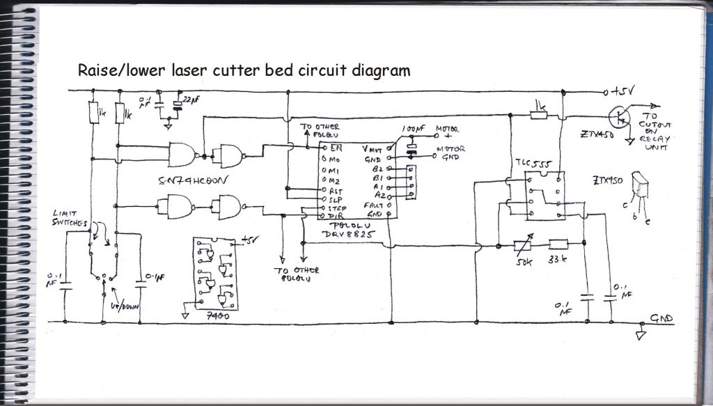
How the circuit works
The switch, bottom left, marked “up / down” is a centre off change over switch. When the switch is off, the inputs to the top 7400 NAND gate are high (courtesy of the two 1k resistors). The second NAND has its inputs connected together to give an inverter, so the output to the Enable on the driver is high and the motor is disconnected. At the same time the low output of the first NAND is linked to the 555 timer (which is wired to produce equal mark/space pulses) reset pin, thus preventing pulses from being generated.
When the switch is operated, the inputs to the NAND are unequal and the output to the driver’s enable pin is driven low, the 555 reset pin goes high producing pulses and the motor runs. One of the poles of the switch is linked to the direction pin on the driver (via the NANDs wired as buffers) so the motor direction changes according to the switch position. Limit switches prevent the bed being moved into the wrong position etc.
The speed of the motor can be set by adjusting the variable resistor on the 555 circuit. The link to the reset pin on the 555 also connects to a ZTX450 transistor which will be connected to the previously described relay board to trip the supplies to the gantry, laser etc. when the bed is being raised or lowered.
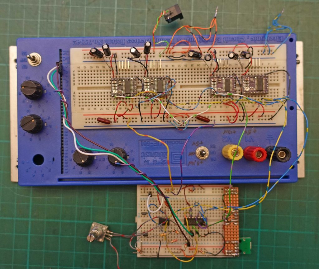
The picture above shows the final circuit breadboard. It’s the usual mess!
PCB design – not my best work!
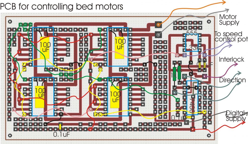
The layout for the bed raising motors is shown above. It is not amongst my best work! It contains masses of wired links. Maybe I should try auto routing? (I made one or two alterations in the final version, cutting the link to half stepping and allowing other modes to be set. I also incorporated the fixed resistor – 33k in series with the variable resistor – on the pcb.)
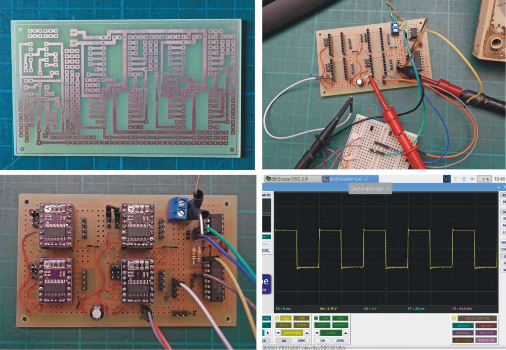
Above, top left: The pcb before drilling. Above, top right: Testing the square wave generating section. I monitored the waveform on my BitScope oscilloscope running on a Raspberry Pi (above, bottom right). Above, bottom left: The pcb with the Pololu circuit boards plugged in.
Expanding the honeycomb
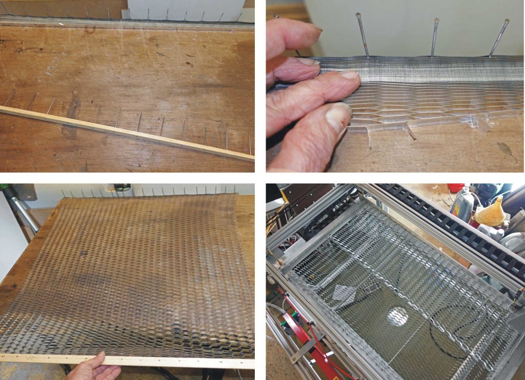
At this stage I tried expanding the honeycomb. I had read the instructions some time previously and thought I could remember what to do. So I trimmed the length of the unexpanded honeycomb with a fine saw. Next, I placed the honeycomb at the far side of my bench and knocked some panel pins through the end cells (see pictures above). Then I knocked panel pins through a strip of wood so the points stuck through the other side. I engaged these with the cells in the honeycomb and pulled gently to expand it. At this point I realised that with the expansion in one direction comes much more contraction in the width of the honeycomb than I had bargained for! I had trimmed off about 25mm more than I should have.
I cut the parts of the honeycomb which had been pulled by the nails as they were a bit uneven. I used a large pair of scissors which produce a surprisingly neat cut.
I tried the honeycomb on the frame and found that the support grid spacings seem suitable to adequately support the honeycomb (unless I want to lase a small piece of something extremely dense!) Of course, one end is not supported because the honeycomb is too short. Rather than modify the support frame, I will probably buy some more honeycomb. Bother!
Next time…
Next time, I will mark out the positions of the panel pins so that the spacing is even (rather than just judging by eye) and use the drill press to make pilot holes for the pins to ensure they are vertcal. This will make it easier to ensure that the honeycomb is expanded evenly.
Strips of aluminium lightly clamping the honeycomb would probably be good thing too.
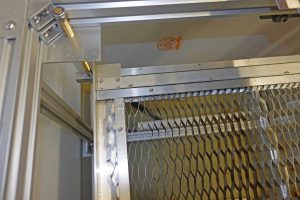
The picture above shows such clips at the bottom left corner (0,0 point for the laser is about 8 mm away from these clamps / stops). These form a good reference point for positioning material to be cut.
Completion of the trunking
Above, you can see the trunking from the gantry to the fixed electronics etc. on the frame. The plate on which the trunking runs can also be seen.
Now I need some plastic conduit to tidy up and protect the rest of all those wires. (Or perhaps it should be metal conduit, grounded to shield all those wires. This brings me to the frame itself. It should probably be grounded but the extrusions are anodised which is an insulating layer. So, perhaps, wires should be attached to the various parts with the anodising scraped off where this contact is made and taken to ground at one point. I’ll leave this till later!)
Mirrors
I read that copper mirrors are good for infra red beams and that they can be made in a home workshop, so, here goes!
I purchased a 25mm diameter bar of copper and sliced off three 11mm sections on my band saw. I rotated the bar (against the motion of the saw – don’t let the saw drag the bar round – this makes a big mess) to try and get as accurate a cut as possible. During this process, I managed to jam the blade on numerous occasions which results in the blade coming off the wheels followed by fiddling to open the case to replace it accompanied by some cursing!
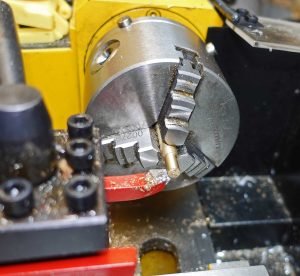
Then I put the pieces in the three-jaw chuck on my mini lathe and cleaned up the cut leaving the pieces about 10mm thick (picture below, top left).
I made a 3D printed clamp with six index holes (at 60 degree intervals) to enable me to drill three holes (separated by 120 degrees) which would then be threaded to take the screws which spring load the mirror onto its bracket (picture below, top right and bottom left).
Having drilled the holes, I tapped them out to M3 with the mirror blank in a drill vice and the taps (starter, number two and bottom) in a drill stand chuck (with the drive disconnected). The helps ensure the holes remain at right angles to the future mirror surface.
I cut another (thinner slice) of the copper bar, fitted it in the clamp and drilled six holes to use as a guide to drilling the holes in the mirror bracket (picture below, bottom right).
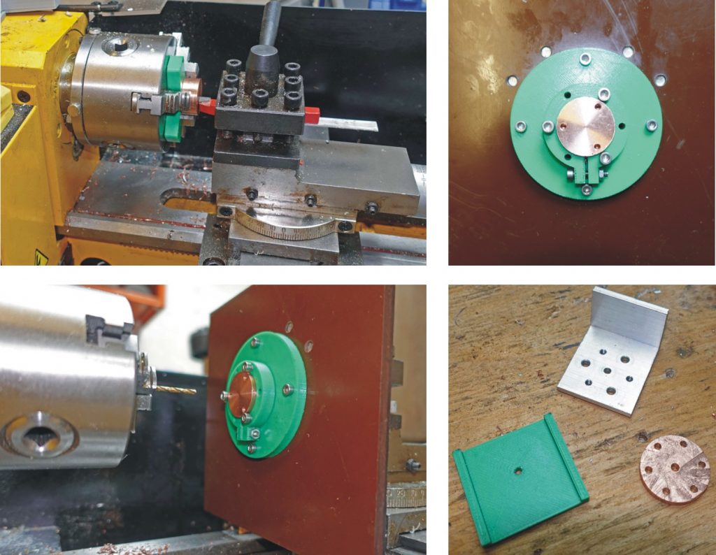
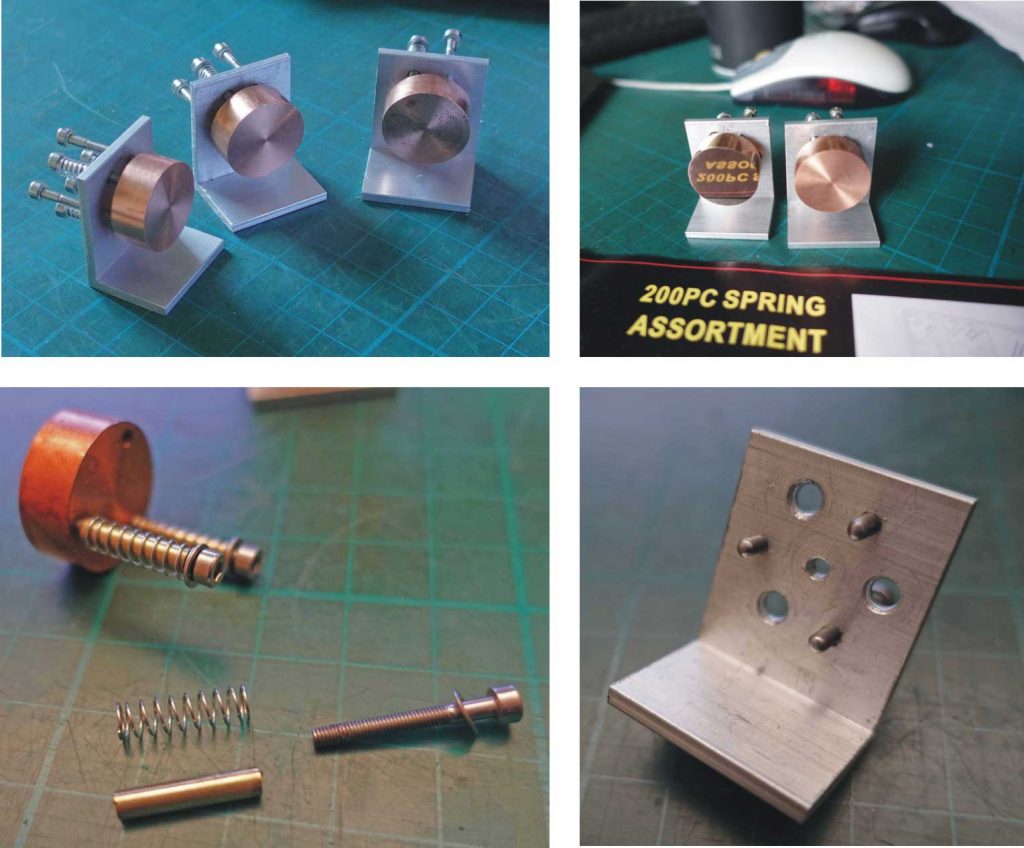
Three M3 cap screws spring-load the mirror while another three bear on the back of the mirror to adjust the aim. To ensure the spring-loaded screws do not drag on the aluminium bracket as they pass through, I included a section of thin-walled brass tube (3mm internal, 4mm external diameter) of the type you can get at model shops. I cut this with a fine toothed piercing saw with a piece of 3mm aluminium rod inside to help to reduce the saw catching when it is half way though.
The 4mm holes in the bracket where the tubes pass through need to be countersunk on both sides to allow the tubes to angle slightly as the mirror is adjusted. A bit of careful filing with a 3mm needle file is also needed to take off the sharp transition between the hole and the countersink.
I also ground the tips of the three adjusting screws into a rounded point which I finished off on a stiff polishing wheel loaded with brown cutting compound (“Tripoli” compound) – see picture below, bottom left and right.
Then I tried polishing the mirror surface. I took a piece of 800 grade wet and dry carbide paper, placed it on the flattest surface I could find (my cast iron saw table) and rubbed the surface in circles and back and forth regularly moving the disc in my hand until the lathe circles were removed and the abrasion of the surface seemed even. I tried to take care that the surface under the paper was clean and free of grit as was the paper itself.
Following this, I polished the surface with Solvol Autosol chrome polish on a cotton cloth, stretched out on a flat surface. After a few minutes, it seemed pretty shiny. I tried using both cerium oxide and tin oxide as a slurry (I had these for polishing semi-precious stones from my jewellery making days) but they didn’t make any noticeable difference (they are used normally for polishing hard materials so, perhaps, no surprise). I should try jeweller’s rouge (ferric oxide), maybe.
There are still scratches visible on the surface. I put this down to the abrasive paper not being free of grit. I will carefully wash a new piece of paper before trying again. (I assume scratches will scatter and generally mess up the beam) – see picture below, top left, unpolished, top right, one polished, one not.
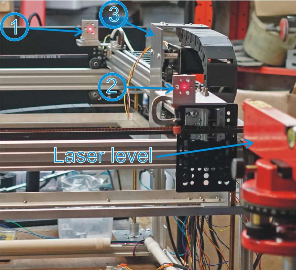
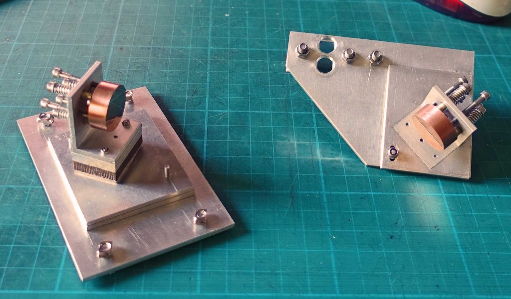
Getting parts in the right position
The next step was to get some idea of where the mirrors would need to be positioned. I made a plate on which the left hand gantry mirror would be fixed and a temporary plate the other end of the gantry. I set up two of the mirror brackets on each of the plates so that each was the same height above and parallel to the gantry (1 & 2 on the picture below). I shone my (very cheap) laser level through each of the centre holes of the brackets (see picture). The plate, 3, is where the third mirror and focussing lens will be attached. I held a ruler at 90 degrees to the plate and measured off where the laser dot struck. This measurement gives the distance of the centre of the mirror and the lens from the mounting plate. The next stage was to make a housing for the mirror and the lens.
The housing for the third mirror and lens
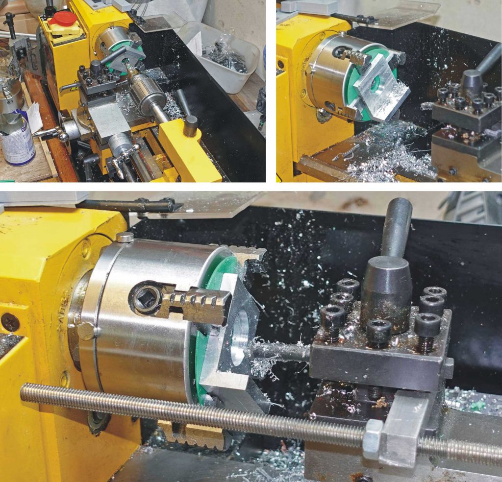
Using the distance determined above, I made a housing for the lens our of a piece of 6mm aluminium angle (see pictures above). I marked the position of the hole for the lens and then mounted the angle in the 4-jaw chuck on my Mini Lathe with the mark at centre height. I included some packing to clear the back of the chuck so it didn’t get damaged when I made the hole. I used a step drill in the tail stock chuck to make as big a hole as possible without hitting the 4-jaw chuck. Then I used a boring tool to enlarge the hole to 23 mm diameter, allowing 1 mm all round to support my 25 mm ZnSe lens (which I trust is suitable!)
The lens has a focal length of 38 mm which I understand will be a compromise between cutting fine detail (smaller focal length) and depth of cut (longer focal length). I was after a 50 mm lens but I could not get hold of one at the time at a reasonable cost. (I did order a 50 mm lens but there was nothing in the box when it arrived!)
Then I enlarged the hole to 25 mm to a depth of 3 mm so the lens would fit in. I also made clamp to hold the lens in place with a recess for a suitable “o” ring. You can see that in the picture below.
Completion of the mirror / lens unit
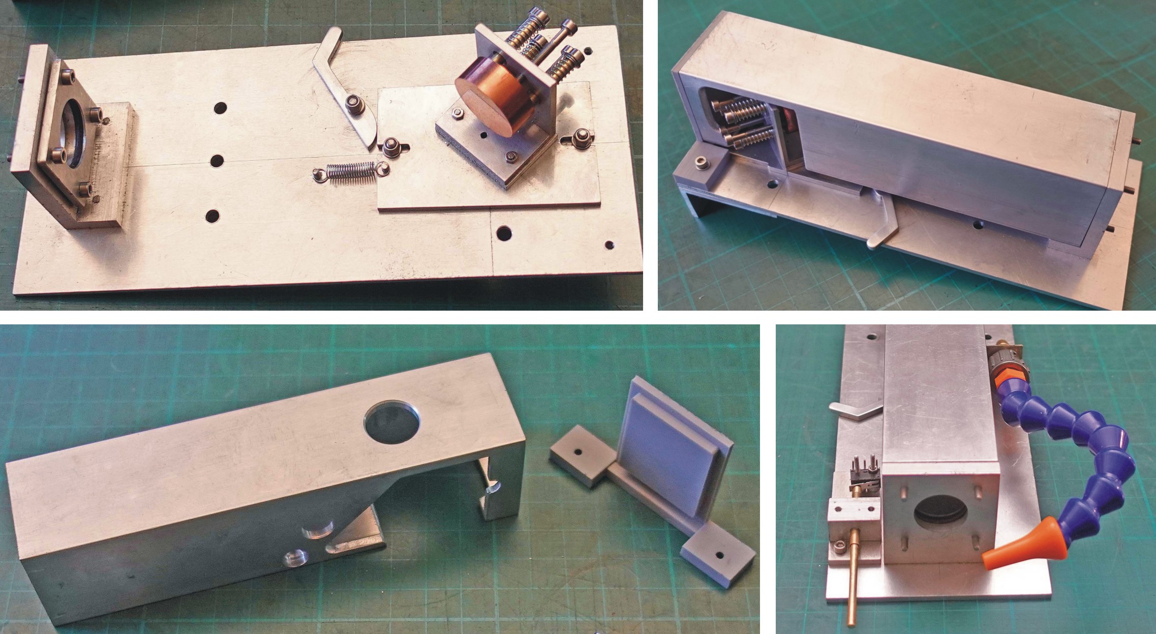
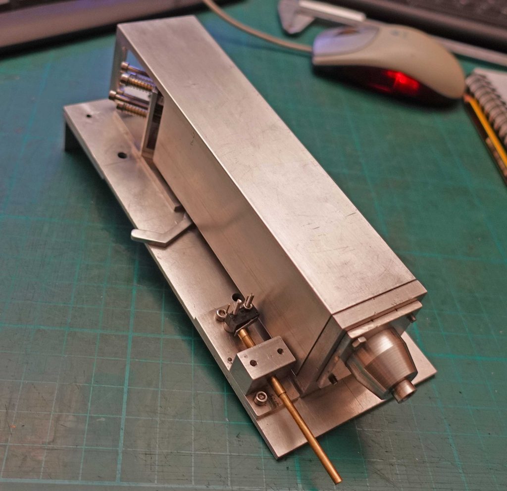
In the picture (above) you can see the lever adjustment for the mirror, a piece of 50 x 50 mm tube cut out to shroud the mirror and lens and a (grey) 3D-printed moulding to retain the tube. Also, a probe to set the table height (operates a micro switch – picture below – this proved to be too long and had to be shortened later) and an adjustable nozzle to direct the air blast (this didn’t work out – see later).
Finally, in this phase, I turned up a shroud for the focussed beam from a piece of aluminium rod. It’s held in place by a plate to the underside of the mirror / lens unit (see picture below).
The picture below shows the completed unit.
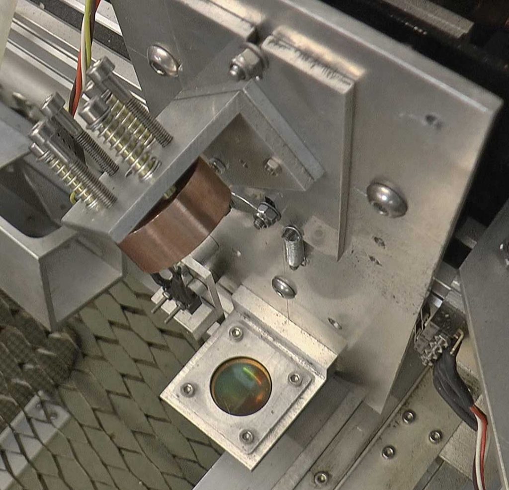
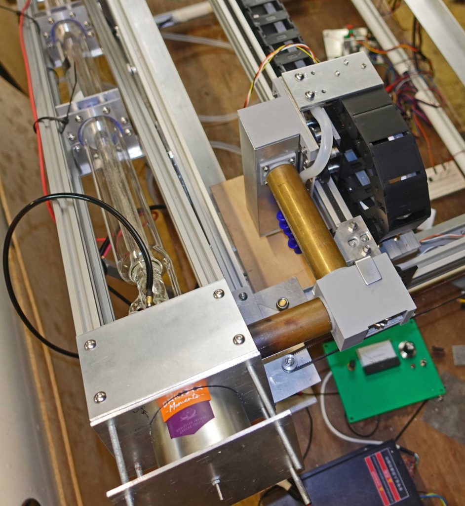
Above: The mirror and lens unit installed on the gantry with the cover removed. This is a later picture and a bit of dirt or soot has accumulated. (Note the two limit switches on the right, one for grbl – via the Arduino Uno – and one for the master stop unit.)
Checking the mirror alignment
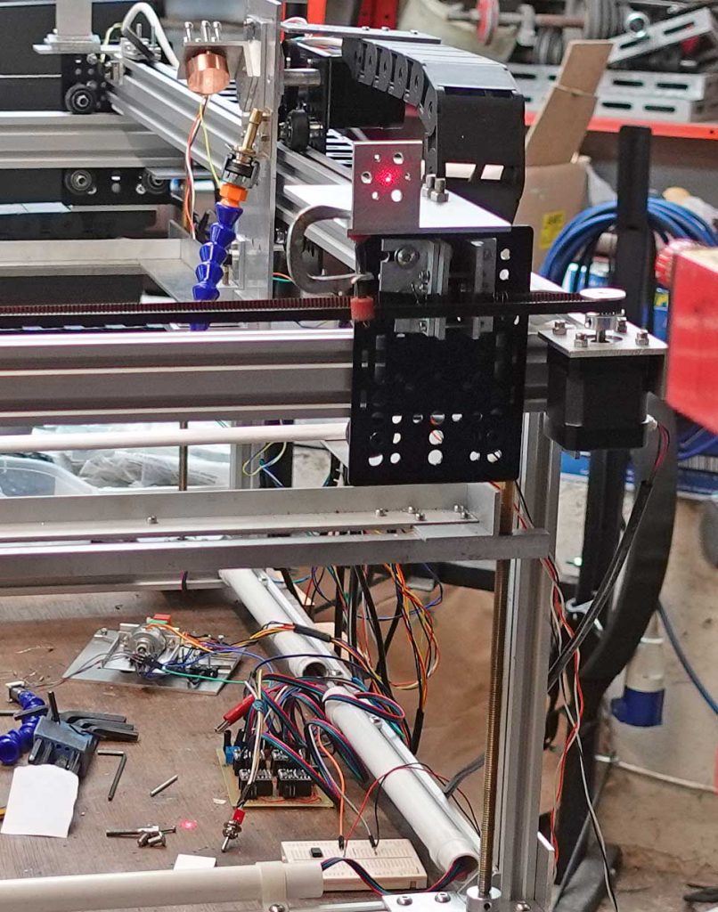
With the laser level still in position to shine through the centre of the second mirror mount and parallel to the gantry (see picture above), I adjusted the lens mirror up and down (with the lever) and adjusted the tilt to get the beam hitting the centre of the mirror and passing through the centre of the lens mount. You can see a red dot on the bench.
Mounts for first and second mirrors
The mirror on the left in the picture above, is the first the laser beam will encounter and will fit in the cradle which will hold the laser (this is described below). The stack of various thicknesses of materials brings the centre of the mirror up to the axis of the laser. The mirror on the right is the second and is mounted on the end of the gantry. The large holes are to allow it to fit over various bits and pieces belonging to the drive belt etc. You can see slots allowing the mirror’s position to be adjusted.

Above: the mirror mounted on the gantry with a cover which I hope will reduce stray reflections while initial adjustments are made and the laser is not in its final box. I will be able to detect misalignment, as this bit of 3D printing will immediately melt (or worse)!
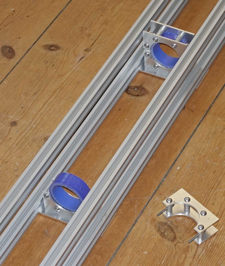
Cradle for the laser
I’ve built a cradle to hold the laser from four pieces of 20 x 20 extrusion joined with pieces of 3 mm aluminium plate. At 1.2 m long, it looks rather large compared to what I have already built. It could have been a bit shorter but I bought the extrusions before I had the laser. I could shorten them but they come from the supplier so neatly cut and all exactly the same size so I am loath do any cutting! (See pictures below.) I am now intending to fit the laser to the rear of the cutter framework at an angle which will save some space. On the plus side, I understand setting the laser at an angle is necessary to prevent air bubbles getting stuck in the glassware. On the other side, however, it will make it more difficult to get the beam from the first mirror, which is in the cradle, lined up as the whole laser, cradle and all will need to be adjusted.
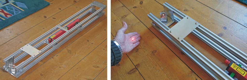
The top pictures show how I have made some adapters to fit the laser level in the cradle and have the beam firing along the centre line like the CO2 laser. That way I hope to do some more preliminary optical alignment.
The picture shows the red dot on my hand. I don’t think I will be testing the real laser like that!
The lower picture shows the details of the clamp for the laser. It seems over complicated but it does work quite nicely. It so happened that I had a piece of silicon tube with an internal diameter of 50 mm which matches the diameter if the laser. I cut sections and split them so they could be put on the laser. I cut 3 mm plates with suitably sized holes and then cut them in half and screwed the parts together with sections of aluminium rod drilled and tapped to M5. The rods were also cross drilled to enable the two halves of the clamps to be screwed together and so that the clamps could be screwed to plates which could be in turn, screwed to the extrusions.
Fitting the cradle to the machine
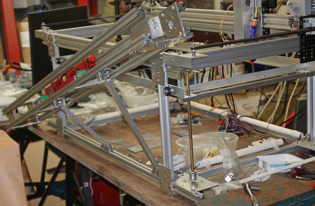
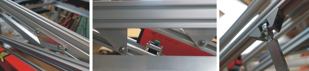
The picture above shows the cradle fixed in place at a jaunty angle! I’ve used three triangular plates and a spacer to clear the guide wheels for the bed. I also have a couple of braces fitted with spherical bearings to cope with the funny angles. These bits and pieces are shown in the picture below.
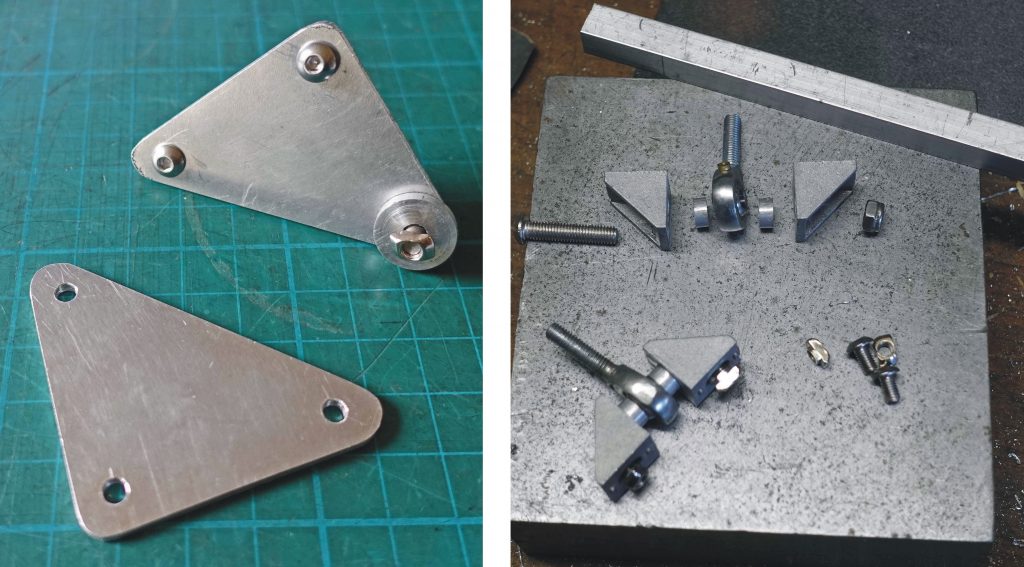
The T-nut with the spacer fits on the main machine frame while the other two fit on the cradle. By sliding and pivoting the attachment points the output from the first mirror should be able to be lined up. The spherical bearings are screwed into tapped holes in the ends of 12 mm aluminium bars (see picture below).
Inital laser tube test
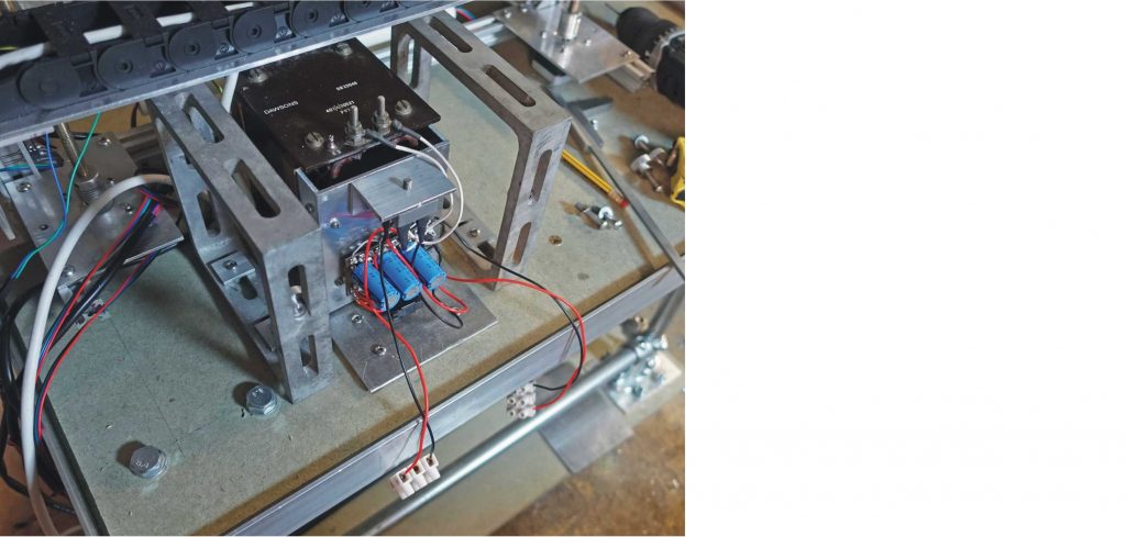
The laser is 1m long, and rated at 60W. I am sure about the length and the fact that it came from China but the veracity of other characteristics remains to be seen! It came from Vevor (on Amazon) and is labelled HK Laser. It cost about £115 and shortly after I had purchased it, this model was no longer available. Make of that what you will! The same was true of the power supply (also from Vevor) which is labelled MYTG60W. This cost £82.
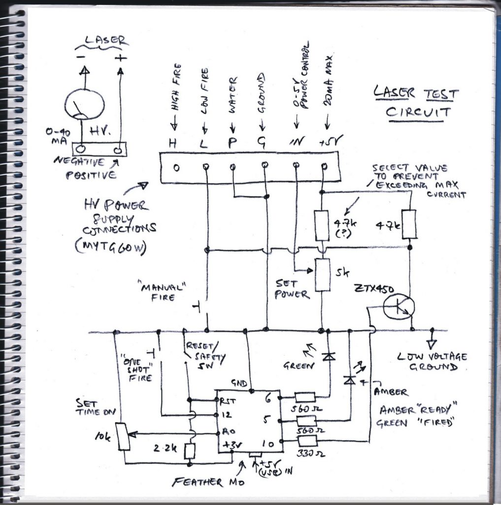
I fitted the laser tube into the cradle and removed the first mirror. I cut an instant coffee can in half, lined it with fire-clay and set it up as a target (“X” in the picture below). I set up a small submersible pump in a bucket and connected it up to the tube. I made up some connections to the power supply including a push-button to fire the laser and a potentiometer to adjust the power (0 – 5v input) and a meter (0 – 40 mA) in the negative supply lead to the laser.
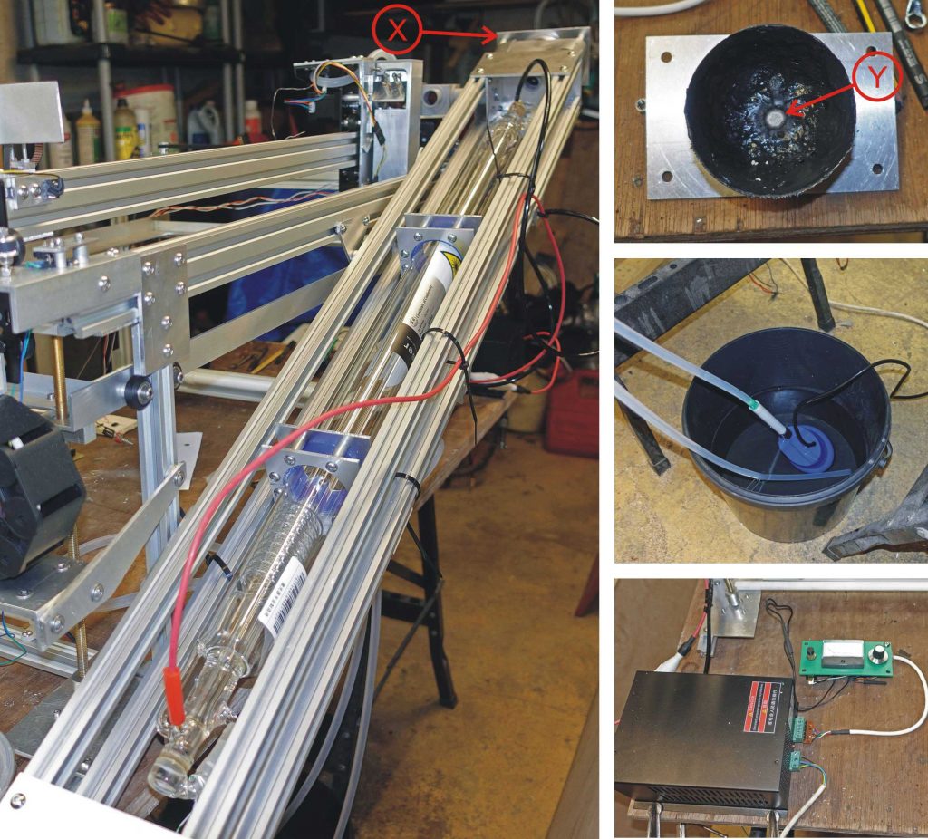
Safety first!
Having donned laser specs, a polycarbonate head shield, gloves etc. I briefly (and with some trepidation) fired the laser at 10mA, blew a hole through a piece of paper and noticed a satisfying pink glow in the tube. I increased the current to 20mA (which the Internet seems to agree is the maximum for a 60W laser) and fired for about thirty seconds. Having removed the plug from the mains, I dismantled the coffee can and noticed how the beam had fused the fire-clay (“Y” in the picture above).
So my fears that either the laser or the power supply or both would be duds were unfounded. Of course, it’s early days!
More testing
For the purpose of testing in relative safety, I protected the optical path between the laser / gantry and the gantry / lens unit with pieces of metal tube (picture above). I fired the laser into a piece of thin plywood set up roughly 38mm from the lens (it’s a 38mm focal length lens) for as short a time as I could physically push and release the button on my temporary laser-handling panel. I was rewarded by a small hole, roughly 0.2mm in diameter (picture below, bottom right). This is perhaps, a bit larger than it ought to be but with further adjustment it will, hopefully, be reduced.
Some details…
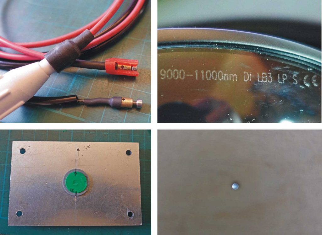
The pictures above show some more details. Top left: The connectors I have made for the laser. Basically, 6mm brass rod, drilled and tapped M3 down the axis and a 2mm hole across for the laser’s pins. The cable is soldered into the rear hole and the joint is protected with shrink tubing. A piece of red silicon rubber tube further protects the positive connection.
Top right: The marking on my laser specs. Radiation from a CO2 laser is at a wavelength of 10600nm so I trust these will keep me safe!
Bottom left: This is an example of 3D-printed buttons I have inserted into various places in the optical pathway to find out where the beam is. In this case, it’s fairly central which is good!
Test circuit details
The circuit below shows the slightly more complex circuit for test firing the laser. I used an Adafruit Feather M0 I had in my bits box to fire the laser once before needing to reset (for safety purposes). The length of the pulse is determined by the software (below). The circuit diagram shows the use of a pot to set the pulse length although, at the time, I didn’t implement this in the software.
Accidental laser triggering
I need to reassure myself that pin 10 does not go high during power up or reset as that would briefly fire the laser. As I understand it, on startup, the input/output pins are in a high impedance state. Although in this state, the voltage on the pin can in theory float above ground it would not be able to provide enough current to turn on the ZTX450 which is a bipolar not FET transistor. A 1k resistor between pin 10 and ground might provide additional insurance against anything untoward at startup or reset.
It would also be a good idea to put an additional push button in series with the “manual fire” button to reduce the laser being accidentally fired.
Software for Feather
// pulses laser once
// 25.1.21

int x = 500;

void setup() {

pinMode(12, INPUT_PULLUP);  // pushbutton fire for x milli sec
pinMode(10, OUTPUT);        // fire psu
pinMode(5, OUTPUT);         // ready to fire led - amber
pinMode(6, OUTPUT);         // finished firing led - green
}

void loop() {
  digitalWrite(5, HIGH);    // amber on
  while( digitalRead(12) == HIGH){      // wait for push button
  }

  digitalWrite(10, HIGH);     // fire psu
  delay(x);
  digitalWrite(10, LOW);    // psu off
  digitalWrite(6, HIGH);   // green on
  digitalWrite(5, LOW);  // amber off
  while(1) {            // loop forever (until reset!)
  }
}
Bit of a lash up?
Maybe I should take more notice of the notice on the high voltage power supply! (Picture below, left.)
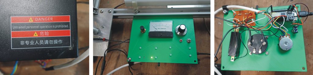
The panel is 3D-printed. It only took seven hours to print! The laser cutter will take a minute? (Even cutting it out by hand would only take an hour or so.) I could have made a much neater job of it but at this stage it will do. ‘Tis enough, ’twill serve, to quote the Bard.
Even worse!
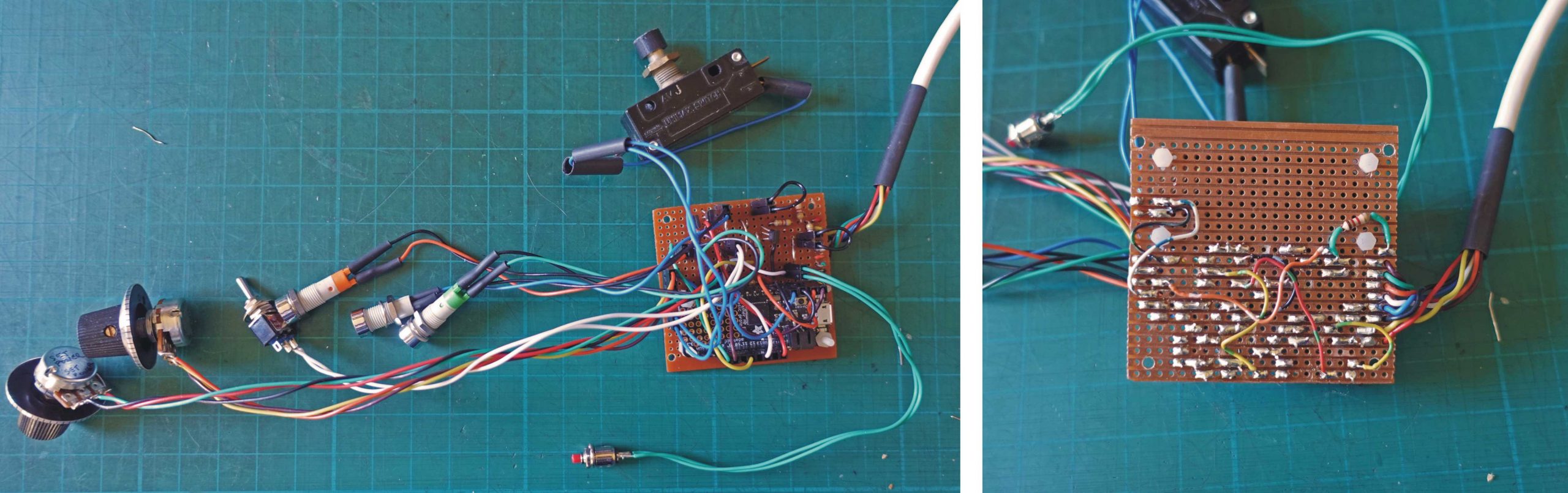
Above, I’ve taken the Feather M0 and the other bits of circuit from the temporary (green) 3d-printed panel and reassembled it all on a piece of strip board (Veroboard). I thought I’d save time and effort making a pcb. It turned out that it took longer to pack everything on the strip board, making up the positioning of the components as I went along. A pcb needs to be designed before manufacture wheras there is a strong temptation to design strip board circuits as you go along. To make final assembly easier (I hope) I have provided headers to plug in all the front panel stuff. Also, I used a piece of strip board which was probably smaller than ideal. All this resulted in a mess of inter connections and a very unsatisfactory looking piece kit all round! However, it works.
I added a 1.2k resistor between pin 12 (the one shot button) and the 3.3v supply rather than relying on the internal pull-up resistor. The internal pull-up is a very high value and I found touching the switch terminals could trigger the Feather. Although once behind the front panel, I wouldn’t be able to touch the terminals, I wouldn’t want to take any chances that the laser might be accidentally triggered.
I also added a bit of circuitry to turn on a blue warning LED when the laser is firing. I probably could have connected the LED between the low laser fire terminal (“L”) and the laser 5v supply but I opted to use a couple of transistors picking up the state of the L terminal and getting their power (and thus the power for the blue LED) from the 5v supply to the Feather (which derives from the hefty low voltage supply for the whole system (described later).
Finally in this section, remember that, at this stage, I have only set up the laser for manual firing (directly switching it on and switching on for a brief adjustable time). Eventually, I’ll have to get my gcode program to do the switching on and off.
Next, I have to actually do some thinking!
Now I’ve sort of got the hang of most of the systems which go to make up the laser cutter, I can move on to a final design. (I say final, I haven’t really had any formal design at all so far, just a rather nebulous idea of what my laser cutter should be like. Perhaps my subconscious has been working on it a bit more thoroughly! I’m a firm believer in letting the subconscious get on with it! Much less effort required.)
Eventually, I’m going to put everything in a box: 1) to protect from the laser beam, direct or scatter etc. and 2) to contain fumes (or even fire) so that they can be reasonably efficiently extracted. My idea is to mount the existing works on a big enough base and set this on a stand, essentially open with a shelf on which the water reservoir, pump and chiller, air pump and extractor etc. can be mounted.
I had toyed with the idea of welding up a frame from 25mm square section tube but to make it a bit easier, I have decided to use a timber-based material for the base and fit 25mm tubular steel legs and bracing using a Key Klamp type joint system.
I initially intended to make up the base from 25mm thick marine ply but local supply seemed to be problematic so I settled on a double thickness of 18mm moisture resistant MDF Lite. I thought of gluing the boards together but in the end decided to use lots of screws in the interests of demount-ability. I think the main thing it to keep the extrusion frame as stable as possible and 36mm of MDF Lite should do that. I’ll cut a 100mm hole in the base to connect up to fume extraction. Perhaps the base should be covered in, say, 22 gauge aluminium sheet for fireproofing although that would be reflective.
Making the base for it
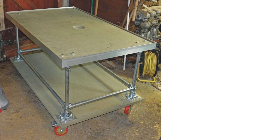
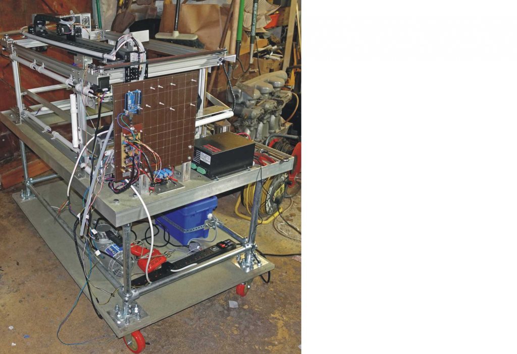
The pictures below show the progress on the laser cutter bench/base. The bottom level consists of a sheet of 18mm MDF Lite and will house the water reservoir, pump and chiller/radiator, the air pump and the fume extractor fan. The frame is made from the Key-Klamp system mentioned above.
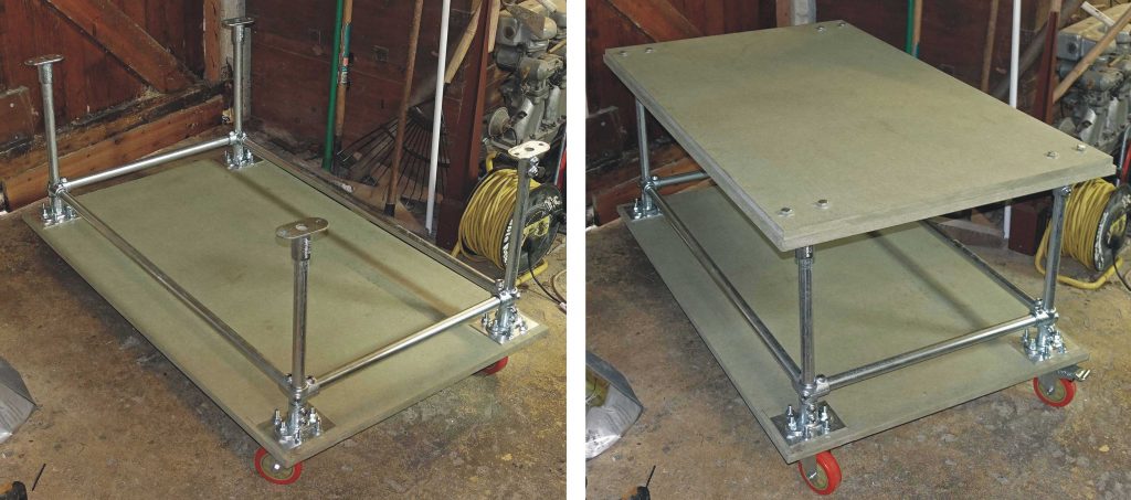
The top (which is the bottom of the laser cutter itself, of course) is made from two pieces of 18mm MDF as mentioned above. The top piece is 6mm all round smaller leaving a rebate to locate the laser cutter case. 50x25x3mm aluminium angle will complete this rebate to form a slot and (hopefully) help to prevent the top from sagging. However, it will probably need some further stiffening underneath. I don’t want the MDF to distort (changes in humidity etc. and distort the laser cutter frame. I haven’t decided whether to bolt the frame down to the MDF or let it “float” on some type of anti-vibration mounting because of these worries!
The overall size of the top is 1220 X 760mm and the whole thing sits on some 100mm castors.
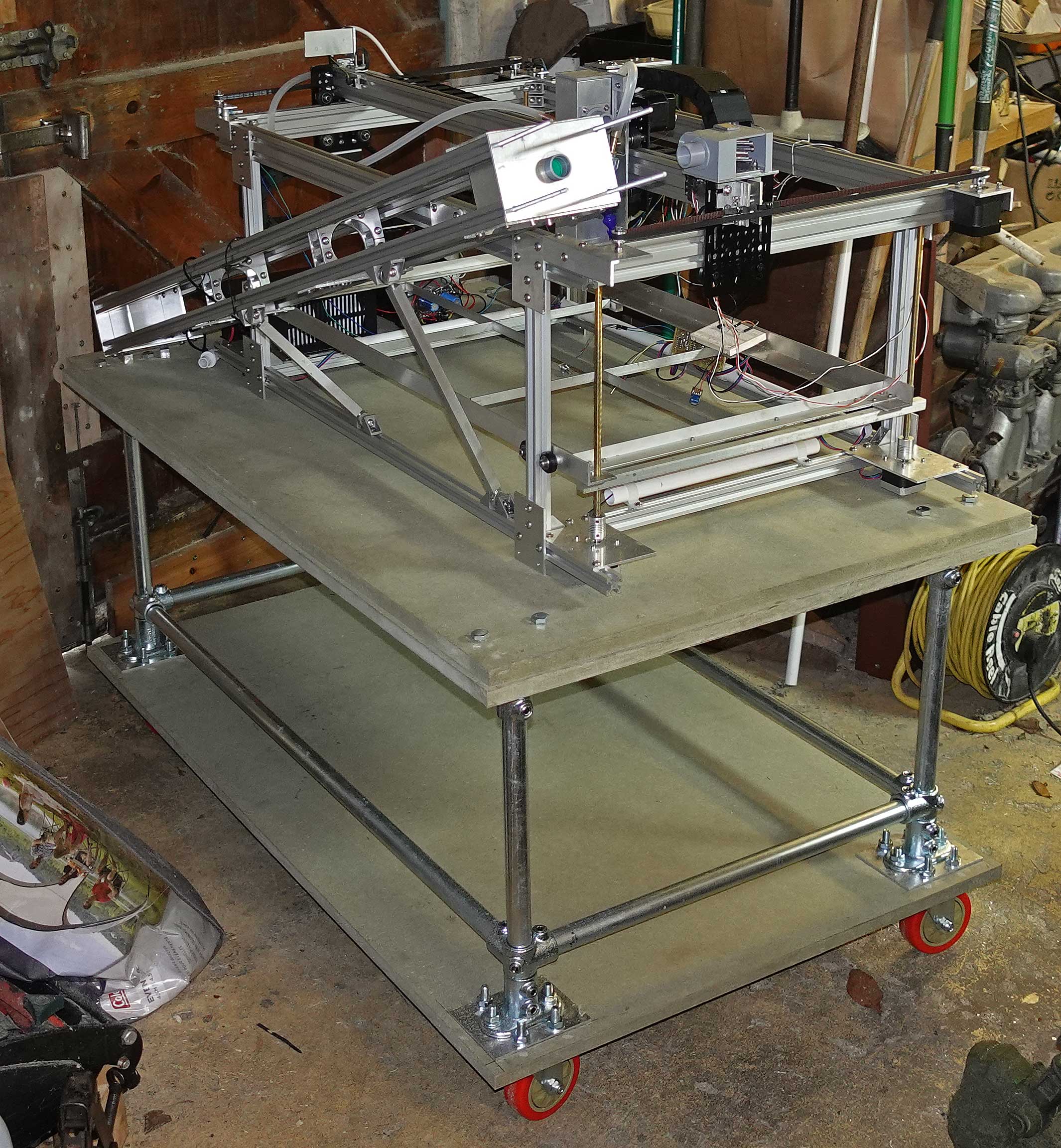
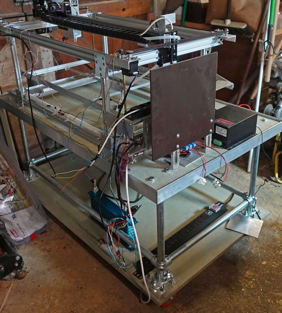
Above: The laser unit sits on its base for the first time! I’m checking to see whether the base is big enough. It is, with room to spare – perhaps I could have made it a bit smaller. Better too big than too small, though (up to a point!) I’m also working out where the 100mm hole for the extractor should be i.e. below he centre of the bed (which is not the centre of the base).
Having worked out where it should be, I cut the hole for the fume extraction with a jig saw fitted with a small trammel bar. I made a bit of a mess of this! I did some tests and everything seemed OK but on the actual job, the blade started to bend and I ended up with a conical hole and a whole lot of rasping, sanding and cursing (50mm radius at this thickness is obviously pushing it). I knew I should have cut the holes in the two layers of MDF separately but I was too lazy! A stitch in time saves nine or something like that!
After all that extra work, I rounded off the top with a router.
Above: I have screwed the two pieces of MDF Lite together with about 24 screws (5mm) and screwed on the 2x1x1/8” aluminium angle round the edge with a lot of 4mm self-tapping screws. The top now shows only a small amount of flex, so further reinforcement may not be required.
(However, much later, I noticed lower shelf sagging. I should have guessed the weight of the compressor, the water reservoir etc. would have been enough to cause this. I tied the shelf to the cross bar with inverted “U” brackets made from 3mm aluminium as shown in the picture below.)
(Yet more) thoughts.
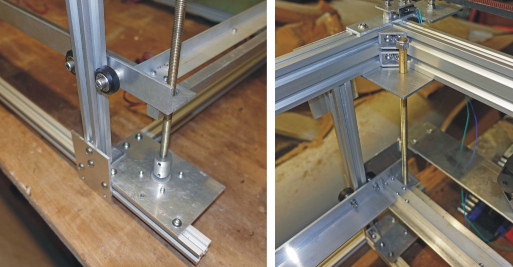
With the unit on the base (now on its castors, I am able to easily reach the back where the laser is for the first time), I began thinking of an easier way to adjust the laser’s position. Pulling and pushing the triangular brackets up and down the extrusions of the cradle and the frame against the effects of gravity was nowhere as easy as I had thought.
With my new idea, I can allow the rear of the cradle to pivot at the level of the base and jack the front end up. That way, by sliding the back end pivot back and forth and jacking the front end up and down, I can (relatively) easily get the output from the first mirror to point in the right direction.
Once in the right place, I can secure the cradle to the main frame with the triangular plates and the spherical jointed braces (that I described earlier) and take the jack away.
Details:-
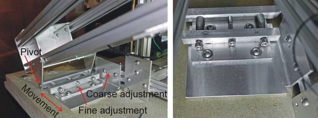
The pictures above show the arrangement of the cradle rear, adjustable pivot. Large movements can be accommodated by sliding the assembly along the extrusion while fine adjustment can be had by adjusting the screws against the retaining springs. As usual, a simple idea seems to get a bit complicated hut, hopefully, it will work!
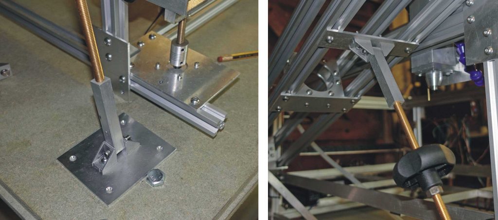
The pictures above show the arrangement to jack up the front of the laser. The brass M8 threaded rod is socketed into one of the 12 x 12mm bars and threaded into the other. The adjustment knob comes from an old lawn mower!
Progress…
Now I’ve just screwed the frame to the top of the base with the 4mm self-tappers. The use of glorified wood screws in this sort of apparatus offends me (should be nuts and bolts) but once you start using not-so-glorified wood (i.e. MDF) as a base, these things probably become inevitable! (Perhaps a nice carbon fibre honeycomb panel in future lives?)
It strikes me, that at some point I will have to get the top of the frame as flat as possible (although I am guessing that with a laser cutter this is not so important as in a CNC milling machine). I am going to use my optical level ( a bit like a theodolite) which is good for getting building foundations level. It might be accurate to half a millimetre or so but unless my workshop floor is very flat (unlikely) moving the thing round on its castors will mess things up.
Wiring it up – at least making a start!
Now, I’m starting getting the electronics and the wiring sorted out. This is more designing it as you go along!
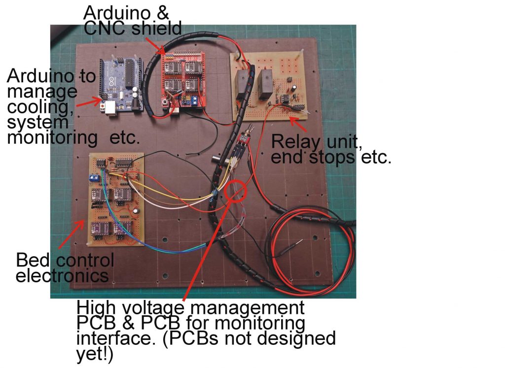
The picture above shows a panel, 300x300x6mm, made of a reinforced plastic similar to Tufnol. This very strong material can be machined drilled and tapped etc. and has a pleasing (to me, anyway) retro aesthetic. A similar material, Paxolin, was much used in the electronics of the past, for example for terminal boards, valve (tube) holder bases etc.
I will be screwing the various circuit boards which make up the electronics onto this panel which will also be the back of a box, the front of which will be the control panel.
Above: The rather hefty brackets which support the electronics panel and the (also hefty) old fashioned transformer which supplies the power for the steppers etc. (These brackets were manufactured by Picador, a long lost British firm which made a great range of cheap tools and engineering component of great use to amateurs like myself – I bought these over fifty years ago!)
I found the transformer in a skip a very long time ago along with two others which have since been re-cycled as scrap. This transformer’s secondary is rated at 22 Amps at about 14 volts. There is no stabilisation so the rectified DC voltage with no load will be over 20 volts. This does not seem to matter as it is the current which counts rather than the voltage with stepper motors (rumour has it). Time will tell! It works fine with the motors for the bed but as yet is untested with the X and Y motors.
There is a 5 volt, 1.5 Amp 7805 regulator for the digital electronics.
In a failure to think ahead about basic practicalities, I protected the supply with a 10 amp (car-type) blade fuse which I fitted in a totally inaccessible position once the electronics panel was in place. I remember thinking that the fuse would never blow but it subsequently did (perhaps I accidentally shorted the supply) leaving me with a lot of disconnections and dismantling. Subsequently, put a 30 amp fuse in the holder and added another 10 amp fuse in an accessible position! We’ll see if that one blows.
Lots of holes – mostly in the right place!
The picture above shows the panel with holes (2.5mm) for the PCBs and holes round the edge tapped to M3 to secure the case sides (which have not been made yet). There are also four 6mm holes to bolt the panel to the quite hefty aluminium frames which support the panel and will be bolted to the base in the fullness of time.
There is also a grid of holes for a couple of PCBs that I have yet to design!
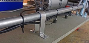
The picture above shows progress with wiring up. It looks a bit of a mess but, hopefully, it will all come together. Wires come from the eight corners of the machine and must be secured so they don’t flap around and get caught up in the mechanics. Where possible, I am fitting pieces of plastic conduit (22mm in the main) secured by ‘p’ clips to the extrusions. These are big enough to easily push the wires and their plugs through.
Diversion – Water pump parts
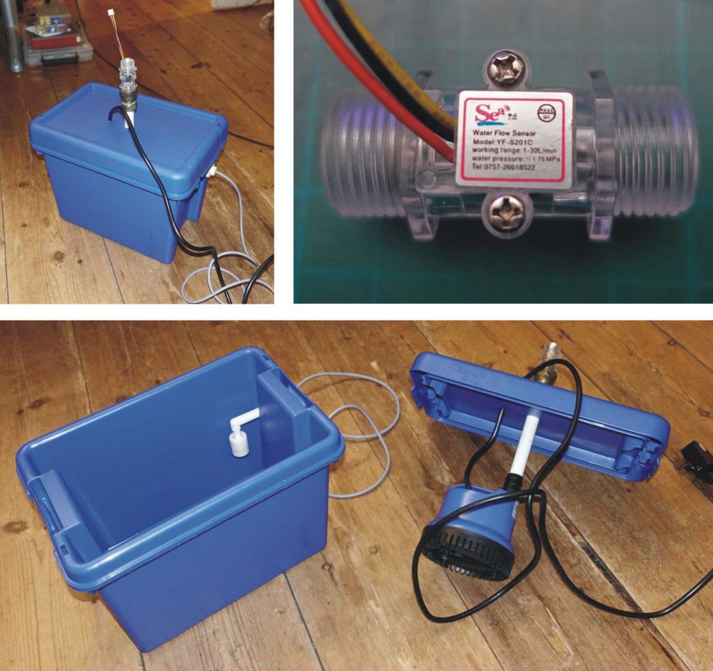
Above are some of the parts for the water cooling system. I am using a small submersible pump (water feature type), in a 6.5 litre plastic box whose colour, as luck would have it, matches the pump! I have fitted a float switch to warn of low water level (probably incorporates a magnet in the float and a magnetic reed switch). I’ve had this knocking about for a long time and can’t quite remember where I got it. Probably from a job lot of electrical parts.
There is also a flow meter which incorporates a little magnetic “fan” which acts on a Hall effect switch (I think) as the water rotates it (Ebay special).
Connectors…
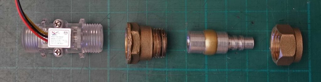
Above: I’ve made a hose connector in aluminium. The cylinder part is 15mm diameter so a standard plumbing compression fitting can be used.
Cool it! (I hope)
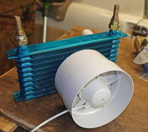
The water will be cooled by a radiator, see picture above (actually a car oil cooler) and a fan (5 inch from Amazon I think). A duct will be needed to optimise the coupling of the fan to the radiator. There will also be a temperature sensor. All the sensors will feed into an Arduino programmed to cut the laser if things go wrong. It will also provide a readout on an LCD screen.
I’ve no idea whether the reservoir is sufficiently large, whether the pump shifts enough water and whether the cooling capacity of the fan will be adequate (this 18 watt, 150mm fan seems a bit weedy). Again, time will tell!
Heat sensor parts
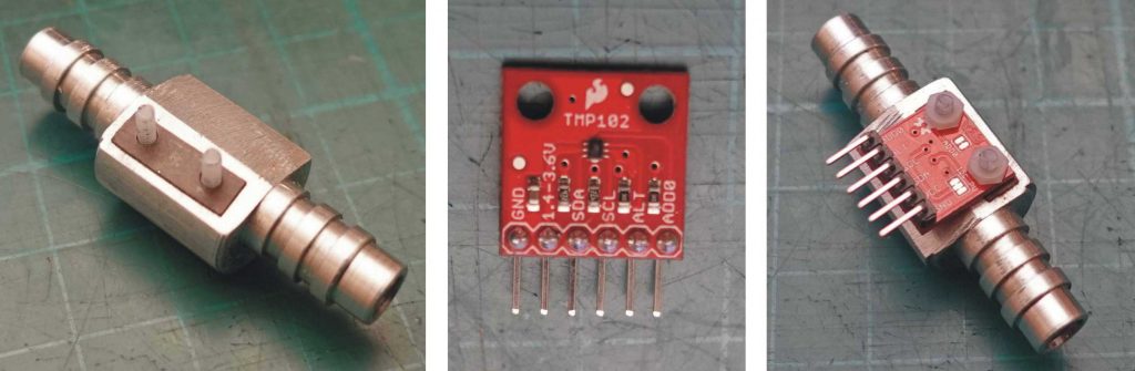
Shown above are the parts for the heat sensor. A thermocouple in the water itself would be best but they are quite expensive and need an amplifier as well. I had a Sparkfun TMP102 breakout pcb which has an I2C output that is very convenient to use with an Arduino etc. This can’t go in the water, of course, but must be in contact with a tube through which the water passes. This introduces a delay in response to temperature changes but I don’t think this will be a problem as I don’t anticipate any very rapid changes in temperature (I may be wrong here, of course – it’s been known!)
To make the sensor, I turned a double ended hose connector from aluminium with the centre left at 19mm diameter. I cut a flat on the centre section with a band saw and drilled and tapped two holes for the TMP102. The idea is to rest the sensor chip on the aluminium. I cut a bevel on the flat to avoid the resistors on the pcb touching the aluminium. I found a very thin piece of Tufnol to space the pcb so that the TMP102 chip rested squarely on the aluminium. I’ll probably use a thin smear of silicon heat conducting paste to ensure good thermal contact and fill the gap between the pcb and the “bevel” with Araldite or silicon filler when I am confident all is well.
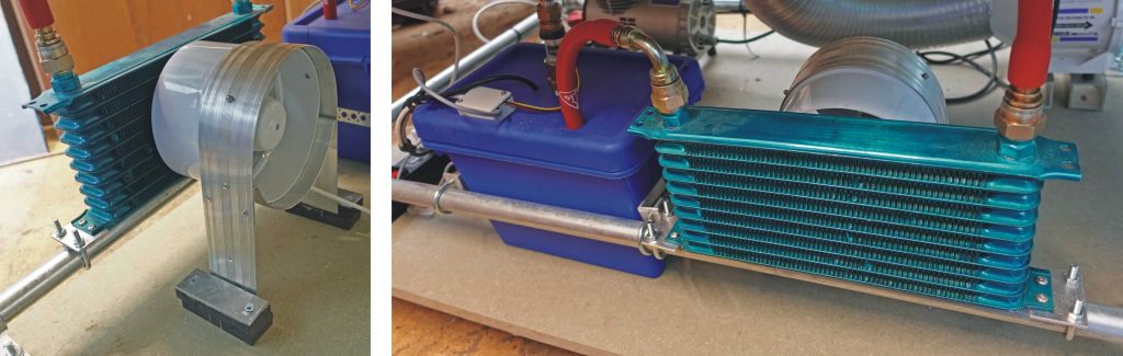
Above: This picture shows the fan and the radiator. The support for the fan is made from a piece of repurposed carpet aluminium threshold strip (not the first time this material has come in handy). It’s held together with pop rivets. The feet of the support are sandwiched between pieces of foam rubber to make an anti-vibration mount. Also in the picture is the blue water tank (with the pump inside). In the end, I just mounted the fan in front of the radiator without any shaped ducting. Seems to work OK (for now, anyway).
Monitoring the cooling system
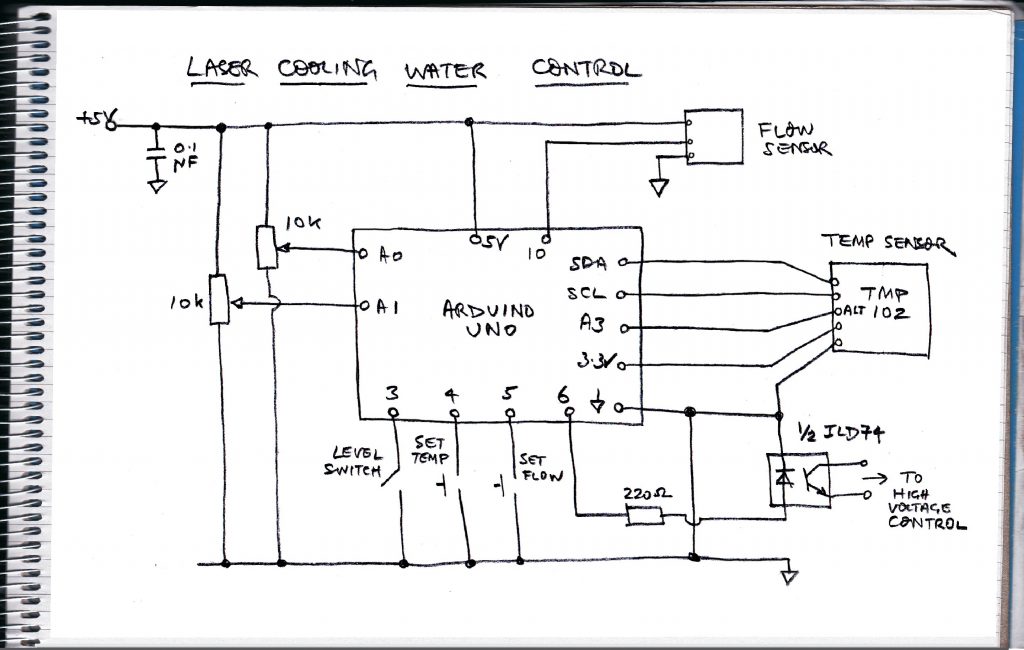
The circuit
I am using another Arduino Uno to monitor the cooling system. The circuit is shown in the picture above, The idea is that when the Arduino starts up, in the setup part of the sketch, the two pots can be used to set the limiting values of temperature and flow. Pressing the buttons stores the values. In the main loop the temperature, flow rate and the state of the water level switch are constantly checked. Any fault results in the high voltage supply to the laser being cut off via the ILD74 opto isolator.
State of system shown on LCD screen
The Arduino is also connected to a 16×4 LCD screen by I2C (not shown in the diagram) so that the values selected by the pots, the current water temperature, flow rate etc. can be seen.
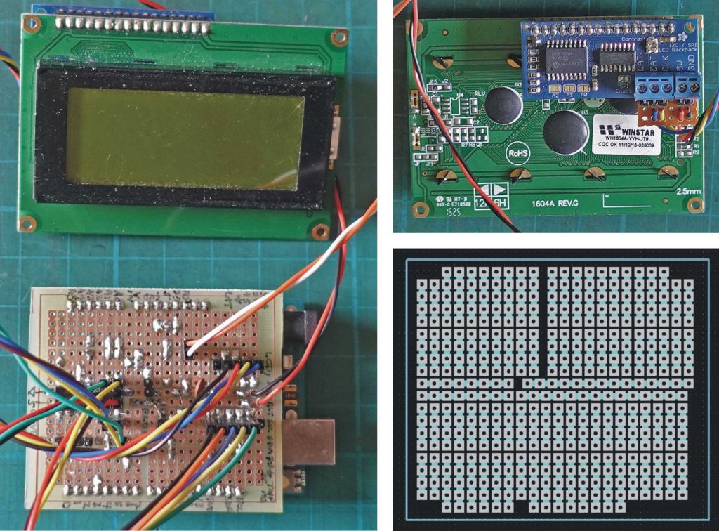
In the pictures above, you can see the bog standard LCD unit with an Adafruit add on which converts it to I2C and provides a handy library for programming purposes.
Arduino sketch
The Arduino sketch for this application is listed below. It includes a number of features provided with the Sparkfun TMP102 library which I have left in but which may not be strictly necessary here.
For some reason, the number of pulses coming from the flow sensor over the 5 second measurement period fluctuates considerably. Is this the sensor / software or the pump etc.? For the time being , to stop the rate dipping below the set minimum, I have used the average of the last five readings as a measure of the flow rate. I have this vague feeling that that is better than just increasing the measurement period from 5 second to 25 seconds.
(If the pump fails at the beginning of a 25 second period, it won’t show up for 24 seconds, lets say. If the pump fails near the end of a 25 second period, it would show up immediately. If the pump fails at the beginning of a 5 second period, it will show up after 4 seconds say but might take another couple of periods for the average to drop below the fail threshold – depending on how that threshold is set.)
Initially, I was going to turn off the laser by connecting to the “water” terminal on the laser psu (labelled “P”). However, I decided to just connect to the master cut out which disconnects the mains 230 volts to the laser psu and cuts the power to the motors. There doesn’t seem to be much point in continuing to move the gantry etc. if the laser is cut. I had to remember that the “water” terminal cuts the laser when high whereas the master cut out/stop unit requires a low. After wondering why it wasn’t working for some time, I did indeed remember! (It requires “HIGH”s and “LOW”s on pin 6 on the Arduino sketch to be swapped.)
//******************************************************************************
// J Rogers
// Laser cutter cooling water system
// 4.8.21
//******************************************************************************
// Fault condition causes loop forever - requires Arduino reset to restore HV (if fault cleared)
// LOW on pin 6 causes (via opto coupler) water pin on HV supply to be high - cuts HV.
// program checks temp and flow and level before initiating HV supply
// (see Adafruit & Spartfun documentation for LCD & TMP102 operation, libraries etc.)
#include <Wire.h>
#include <SparkFunTMP102.h>
#include <Adafruit_LiquidCrystal.h>
int f0;
int f1;
int f2;
int f3;
int flow = 0;
int aVflow;
int maxTemp = 25;
int minFlow = 35;
unsigned long flowTime;
bool wTemp = false;
bool wFlow = false;
bool wLevel = false;
Adafruit_LiquidCrystal lcd(0);
TMP102 sensor0;
const int ALERT_PIN = A3;
//---------------------------------------------------------------------
void setup() {
Serial.begin(115200);     // serial only used for testing - could be cut
Wire.begin(); //Join I2C Bus
// set up the LCD's number of rows and columns:
lcd.begin(16, 4);
pinMode(ALERT_PIN,INPUT);  // Declare alertPin as an input
pinMode(3, INPUT_PULLUP);  // water level switch
pinMode(4, INPUT_PULLUP);  // confirm max water temp
pinMode(5, INPUT_PULLUP);  // confirm min flow rate
pinMode(6, OUTPUT);        // cut HV on fault condition, LOW produces HIGH at HV control
// via the opto coupler
pinMode(10, INPUT);        // input from flow sensor
digitalWrite(6, HIGH);  // start off with HV cut
//Return true on success or false on failure to communicate
if(!sensor0.begin())
{
Serial.println("Cannot connect to TMP102.");
Serial.println("Is the board connected? Is the device ID correct?");
while(1);
}
Serial.println("Connected to TMP102!");
delay(100);
// Initialize sensor0 settings
// These settings are saved in the sensor, even if it loses power
// set the number of consecutive faults before triggering alarm.
// 0-3: 0:1 fault, 1:2 faults, 2:4 faults, 3:6 faults.
sensor0.setFault(0);  // Trigger alarm immediately
// set the polarity of the Alarm. (0:Active LOW, 1:Active HIGH).
sensor0.setAlertPolarity(1); // Active HIGH
// set the sensor in Comparator Mode (0) or Interrupt Mode (1).
sensor0.setAlertMode(0); // Comparator Mode.
// set the Conversion Rate (how quickly the sensor gets a new reading)
//0-3: 0:0.25Hz, 1:1Hz, 2:4Hz, 3:8Hz
sensor0.setConversionRate(2);
//set Extended Mode.
//0:12-bit Temperature(-55C to +128C) 1:13-bit Temperature(-55C to +150C)
sensor0.setExtendedMode(0);
// set max temp and min flow
while( digitalRead(4)){
maxTemp = map(analogRead(A0), 0, 1023, 20, 50);
lcd.setCursor(0,0);
lcd.print("Set max temp    ");
lcd.setCursor(0,1);
lcd.print(maxTemp);
}
while( digitalRead(5)){
minFlow = map(analogRead(A1), 0, 1023, 20, 50);
lcd.setCursor(0,0);
lcd.print("Set min flow    ");
lcd.setCursor(0,1);
lcd.print(minFlow);
}
//set T_HIGH, the upper limit to trigger the alert on
sensor0.setHighTempC(maxTemp); // set T_HIGH in C
//set T_LOW, the lower limit to shut turn off the alert
sensor0.setLowTempC(maxTemp - 1); // set T_LOW in C
lcd.clear();
// check flow rate
// count number of pulses from sensor in 5 secs
f0 = 0;
flowTime = millis()+ 5000;
while(millis() < flowTime){
if(digitalRead(10) && millis() < flowTime){
f0++;
}
// wait for pulse to end
while(digitalRead(10) && millis() < flowTime){
}
}
f1 = 0;
flowTime = millis()+ 5000;
while(millis() < flowTime){
if(digitalRead(10) && millis() < flowTime){
f1++;
}
// wait for pulse to end
while(digitalRead(10) && millis() < flowTime){
}
}
f2 = 0;
flowTime = millis()+ 5000;
while(millis() < flowTime){
if(digitalRead(10) && millis() < flowTime){
f2++;
}
// wait for pulse to end
while(digitalRead(10) && millis() < flowTime){
}
}
f3 = 0;
flowTime = millis()+ 5000;
while(millis() < flowTime){
if(digitalRead(10) && millis() < flowTime){
f3++;
}
// wait for pulse to end
while(digitalRead(10) && millis() < flowTime){
}
}
}
//----------------------------------------------------------------------
void loop(){
float temperature;
boolean alertPinState, alertRegisterState;
// Turn sensor on to start temperature measurement.
// Current consumtion typically ~10uA.
sensor0.wakeup();
// read temperature data
temperature = sensor0.readTempC();
// Check for Alert
alertPinState = digitalRead(ALERT_PIN); // read the Alert from pin
alertRegisterState = sensor0.alert();   // read the Alert from register
// Place sensor in sleep mode to save power.
// Current consumtion typically <0.5uA.
sensor0.sleep();
// Print temperature and alarm state
Serial.print("Temperature: ");
Serial.print(temperature);
Serial.print("\tAlert Pin: ");
Serial.print(alertPinState);
//Serial.print("\tAlert Register: ");
//Serial.println(alertRegisterState);
// check flow rate
// count number of pulses from sensor in 5 secs
flow = 0;
flowTime = millis()+ 5000;
while(millis() < flowTime){
if(digitalRead(10) && millis() < flowTime){
flow++;
}
// wait for pulse to end
while(digitalRead(10) && millis() < flowTime){
}
}
aVflow = 2*(flow + f3 + f2 + f1 + f0)/5;
f0 = f1;
f1 = f2;
f2 = f3;
f3 = flow;
Serial.print("Flow = ");
Serial.println(aVflow);
lcd.setCursor(0,0);
lcd.print("Temp  ");
lcd.print(temperature);
lcd.setCursor(0,1);
lcd.print("Flow  ");
lcd.print(aVflow);
lcd.setCursor(-4,2);
lcd.print("Level ");
lcd.print("OK");
// Check temperature not over limit
if(alertPinState){
lcd.setCursor(-4,3);
lcd.print("FAULT: temp");
digitalWrite(6, HIGH);  // cut high voltage
while(1){
// loop forever
}
}
else{
wTemp = true;
}
//Flow too low...
if(aVflow < minFlow){
lcd.setCursor(-4,3);
lcd.print("FAULT: flow");
digitalWrite(6, HIGH);    // cut high voltage
while(1){
// loop forever
}
}
else{
wFlow = true;
}
if(digitalRead(3) == HIGH){
lcd.setCursor(-4,2);
lcd.print("Level ");
lcd.print("LOW");
lcd.setCursor(-4,3);
lcd.print("FAULT: level");
digitalWrite(6, HIGH);    // cut high voltage
while(1){
// loop forever
}
}
else{
wLevel = true;
}
if(wTemp && wFlow && wLevel){
digitalWrite(6, LOW);  // All ok so initiate HV supply
lcd.setCursor(-4,3);
lcd.print("SYSTEM OK");
}
}
//------------------------------------------------------------------------
Construction
I have designed a cross between Veroboard (strip board) and an Arduino proto shield to connect up the Arduino to the outside world. (Although the pins are standard 0.1 inches apart, the groups are displaced by multiples of 0.5 inch so straight Veroboard will not do.) With surprisingly large number of wired links between tracks I seemed to need, it would have been better to have designed a pcb dedicated to this application but I suppose I could use the design on some other project.
A problem with this pcb is that it needs header pins on both sides, so some will have to be soldered on the track side. This is a bit of a pain as the pins have to be pushed through the plastic separator so that whole pin is sticking out of the bottom (of the separator). They can then be inserted in the pcb, from the track side, prevented from completely passing through (by a piece of tape, perhaps), soldered and the separator pushed back down. It’s all a bit of a mess, I’m afraid! In the past, I have made two-sided pcbs but the fiddle is mostly not worth the bother for my simple stuff.
The controls and display for the water control system are shown below. (Details of the construction of the actual control panel follow later.)
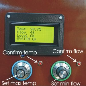
Cooling conclusions
It’s a bit difficult to say exactly how well the system is working as I am writing this in late Autumn and the temperature of the cooling water starts off at about 12 – 13 degrees C. Using this for hobby purposes I see the temperature rising to 17 or 18 degrees after (for me) a longish cut. It drops back in between cuts (the cooling system runs whenever power is on as opposed to the air assist and extraction which only operate when the laser is on). I am also in the dark as to the maximum temperature at which the laser will still operate. So watch this space… (in the Summer).
If I were making this again, I would not bother with the manual adjustment of levels of temperature and flow but would preset values into the software. I would position the various microprocessors so that their programming ports were accessible without dismantling the casing etc. so these preset values could be easily changed (via the Raspberry Pi).
Fitting the RPi in position
Just now I am fitting up the Raspberry Pi computer (most of it, physically, is the monitor and keyboard, of course) onto the unit. It will sit on a Kee Klamp type pole clamped to one of the uprights of the laser cutter base/trolley. I’m not sure about the aesthetics (will look a bit agricultural?) but it should be adjustable and reasonably ergonomic (I hope). I need the Pi in position so I can check that the gantry will still move with all the extra weight of all the bits and bobs I have added since my drawing tests previously described.
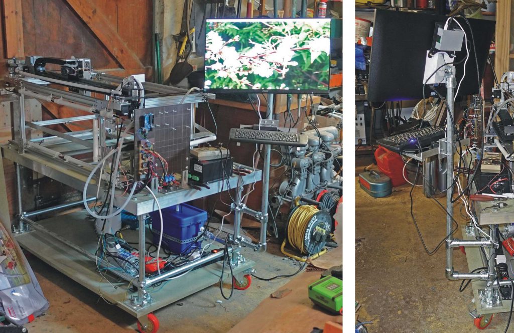
With this project, I have been introduced to the tube and clamp system for the first time. The type I have used (there are several other very similar types, I think, see here ) is Interclamp from www.themetalstore.co.uk. These are certainly robust but the hole for the fittings is rather large for the specified tube and this can lead to a lack of precision which is noticible in small structures in particular. The add-on “T”s are also a bit wobbly. The lack of precision results from the fact that the holes for the tube are “as cast” and not machined (I guess for cheapness). Just saying. I remember working with some aluminium scaffolding towers in a past life (restoring the Royal Pavilion, Brighton). The fittings were beautifully made and, I suppose, I was expecting that with the Interclamps.
I’ve made a simple support for the keyboard using a piece of angle and two pieces of ½ x ½ inch aluminium bar. The support fits in between the feet which locate it. I like this small keyboard, especially for this application. It features a roller ball on the right and two “mouse” buttons on the left. You can pick it up and operate the ball and the buttons with your thumbs while holding it. In my messy workshop, a mouse would be impractical and the Pi “official” touchscreen is too small for any detailed work.
I have fitted the keyboard support to the monitor pole with U-bolts for the time being. Eventually, when I send in my next order to the Metal Store, I’ll get some fittings that will allow the keyboard to swing round the pole more easily, like the monitor.
In the meantime, I can go ahead and test my gantry movements. First, however, I will have to change config.h in the GRBL setup not to move z to clear the work space and recompile GRBL on the Arduino.
Catchup…
But first, a catchup, in picture form, showing construction progress so far.
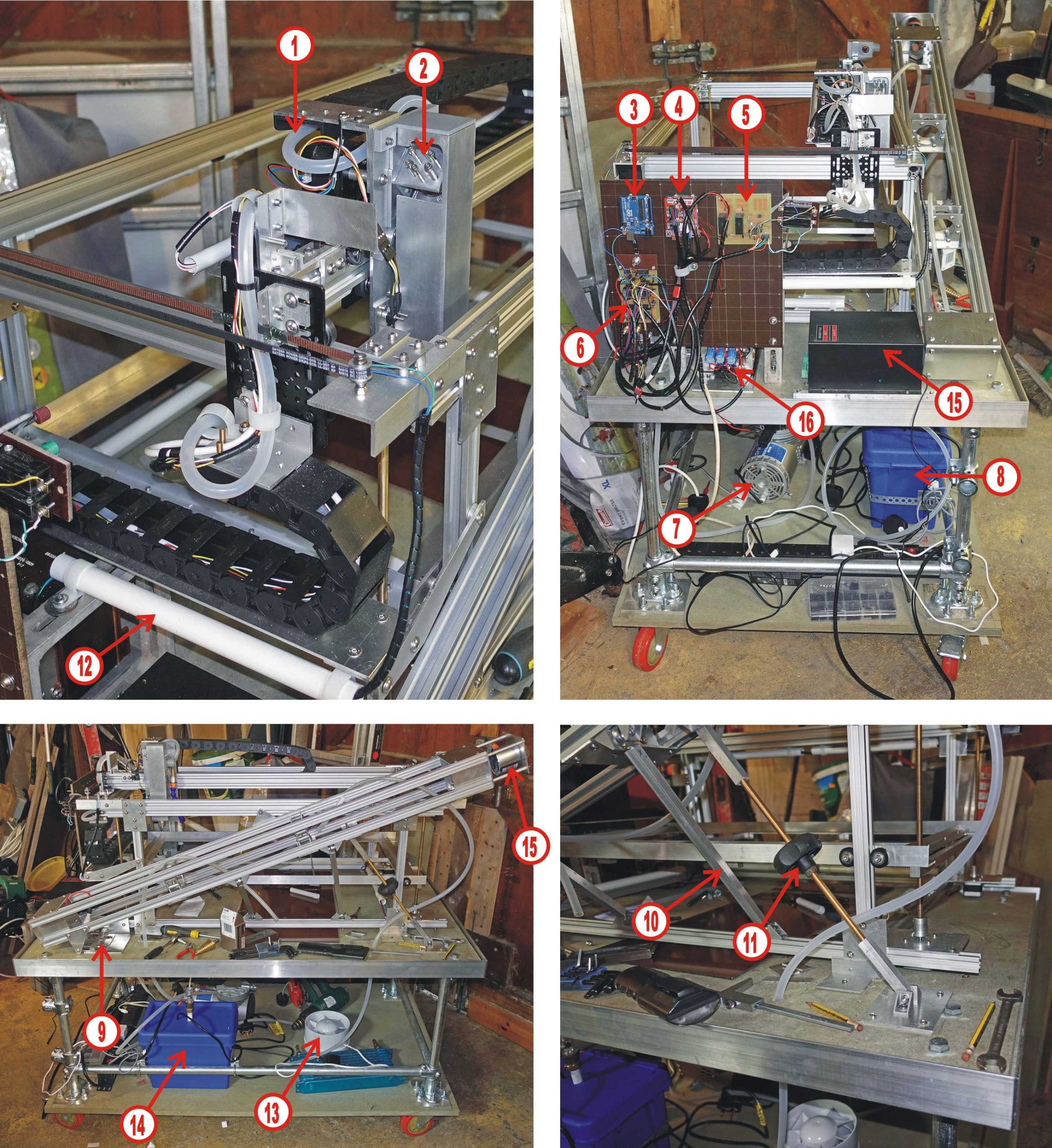
Key to the above…
- Compressed air tube.
- Lens unit mirror.
- Arduino – monitors water flow, temperature, tank level etc.
- Grbl Arduino and CNC Shield.
- Pcb – monitors limit switches, trips high voltage power supply etc.
- Pcb – drives bed stepper motors.
- Air compressor – not yet positioned
- Cooling water tank.
- Laser cradle adjustment, horizontal.
- Laser cradle brace (one of two).
- Laser cradle adjustment, angle.
- Section of cable conduit.
- Water cooling radiator and fan – not yet positioned.
- Cooling water tank.
- Target for testing laser (Aldi coffee can).
Interclamp fittings for monitor & keyboard
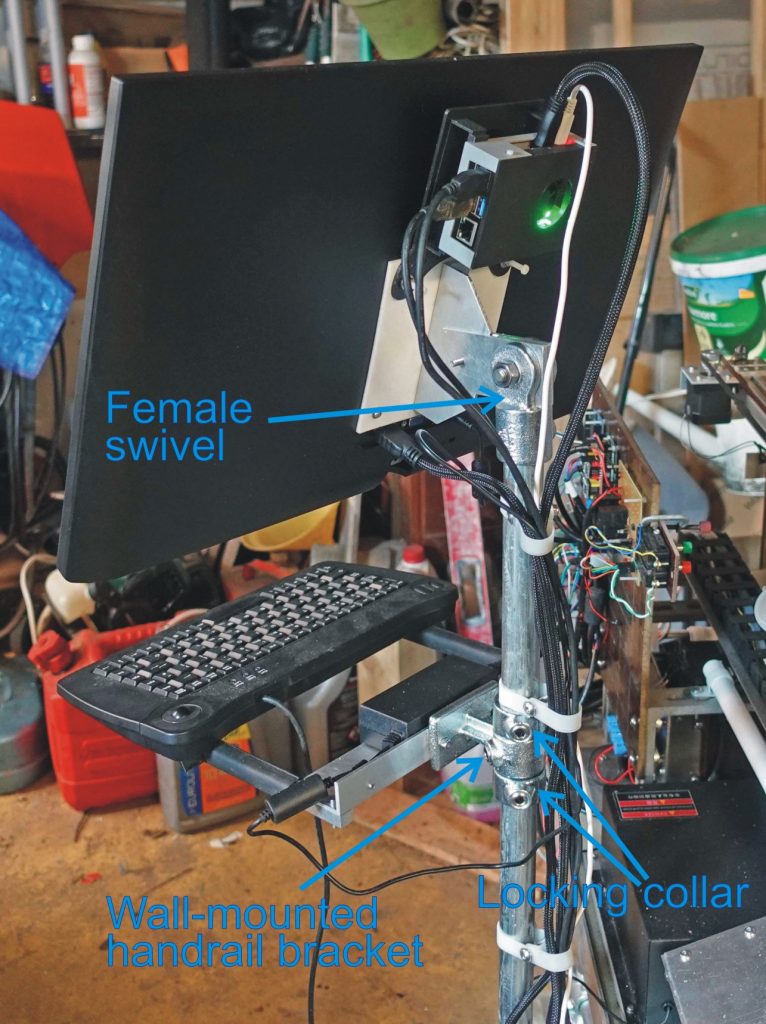
The picture above shows the Interclamp fittings I used to replace the U-bolts I mentioned earlier to hold the keyboard (these are the names of the fittings as listed in the on-line catalogue). The female swivel needs to be packed out with a piece of shim (cut from a drinks can) to prevent slop as it revolves round the vertical tube.
Also to be seen are the sections of bicycle inner tube fitted over the ½ x ½ inch “prongs” on which the keyboard sits which provide grip and a bit of give.
Making the control panel
Next, I’ll be making the front panel to the electronics unit which needs to accommodate the various switches, potentiometers, the LCD screen and the laser current meter. As is often the case with my projects (which are usually designed as I go along), I seem to find that I haven’t got enough space to make the placement of these items straightforward! One of the causes is the number of wires connecting everything up. I’ve grouped these together fairly logically and separated them with spiral binding which adds considerably to the bulk. However, fingers crossed, I can get it all in!
The panel itself locates in the slot round the edge of the base board and is fixed at the top with a couple of pieces of M5 studding. Ultimately, the edge of the panel will locate with the case by means of some sort of H section aluminium extrusion. (Exactly how I will make the case and in what material is still up for grabs!)
Stress, stress, stress!
I seem to have spent more time worrying about positioning the controls on the front panel than about any other part of the design. I probably should have used CAD (and a laser cutter to cut out the holes in the panel – if only I had one of those!) However, it seemed easier to cut a trial panel out of hardboard and test it out. Another of the problems is the available depth. I have to make sure the pots, switches etc. don’t foul the pcbs.
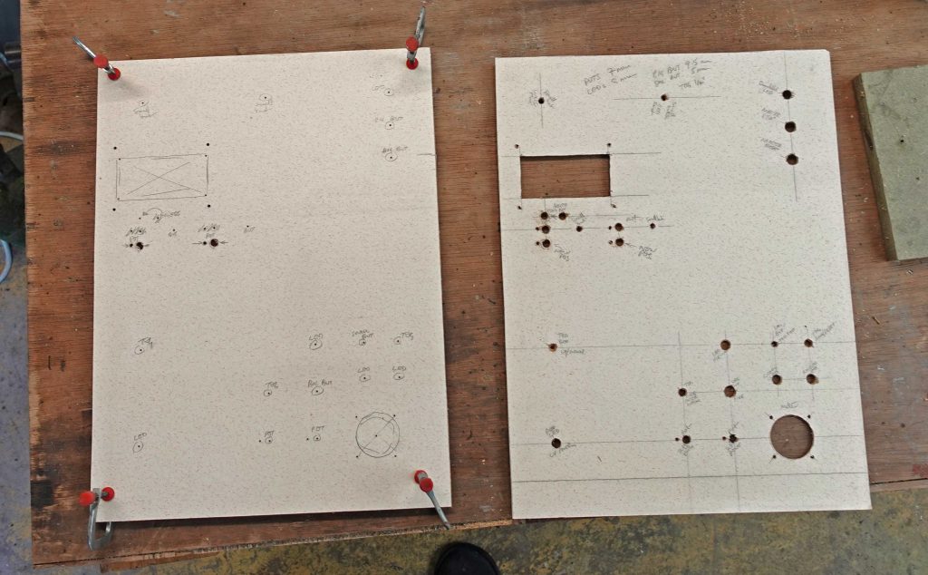
In fact, I made two hardboard panels, one with just the pilot holes for the components (1.5mm) and one with the full size holes and cut outs. The first panel could then be used as a pattern to drill pilot holes in the real front panel.
The real front panel is more Tufnol-type composite. This particular grade is rather brittle and chips quite easily when it’s drilled or cut. Fortunately, none of this can be seen when the components are in place. I made the rectangular for the LCD panel with a fret saw and the hole for the meter with a fly cutter fitted into a brace.
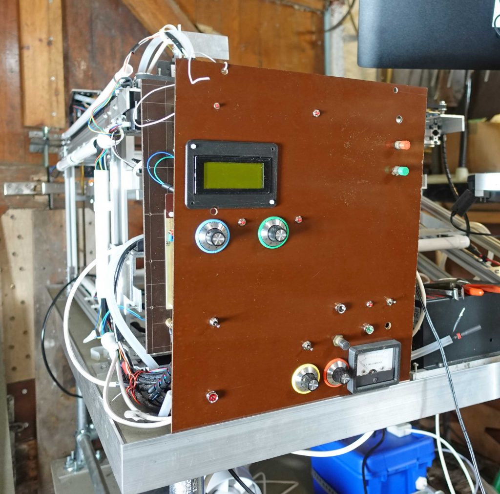
The picture above shows the panel almost completed. The arrangement was dictated mainly by proximity to the circuit boards behind. It’s not very aesthetically pleasing but the asymmetrical placing at least makes it easier to remember what each switch etc. is supposed to do.
However, as I come to make modifications etc. on the electronics, I find myself more and more irritated with my “design”. Ah well, I’ll improve it in the Mk2 version during future lives!
Trial run
Anyway, all seemed well with the mechanical side of things. I could load a drawing on grbl / bCNC on the Pi and have it run with all the correct movements of the gantry etc. However, when I fired the laser, the Pi’s screen blanked off and everything stopped. When I cut the laser, the screen returned as before but with an alarm condition on bCNC / grbl.
My first thought was that the laser must radiate a large amount of RFI which was swamping something in the Pi (presumably in the video side of things).
I grounded all the metal work and wrapped the laser and the Pi in kitchen foil as completely as I could. When I fired the laser, after all this taradiddle, I found the video no longer blanked but the bCNC / grbl still showed an error, G43.1 and text describing a hard limit had been triggered.
I immediately assumed the error was to do with the X or Y-axis limit switches connected to the CNC Shield, so I added 100nF capacitors to each end of the wires connecting the micro-switches to the Shield. It made no difference. Then I realised that G43.1 is concerned with the Z-axis. Nothing is connected to the corresponding pins on the CNC Shield and config.sys eliminates the Z-axis from homing etc. but it turns out that they are still active, so they also need 100nF capacitors to ground.
Later, when I get the gcode to switch on the laser, the Z limit connection (which is D11 on the Uno) will become a pwm output controlling the intensity of the laser and will no longer be a point of entry for RFI (I hope!)
While I was about it, I did the same for the CNC Shield +X and +Y connections (for limit switches I have not connected – you may remember I rely on limit switches connected to my relay board to cope with excursions beyond the maximum travel beyond the X and Y home position). (I now realise these connect to only one X and one Y pin on the Arduino Uno so I’m just connecting two 0.1 uF capacitors in series here!)
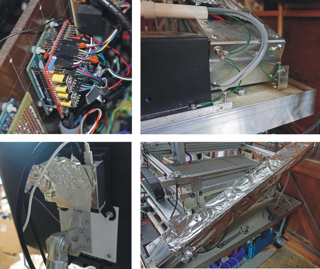
This seemed to solve the problem and I was able to make a test cut in some thick paper/card.
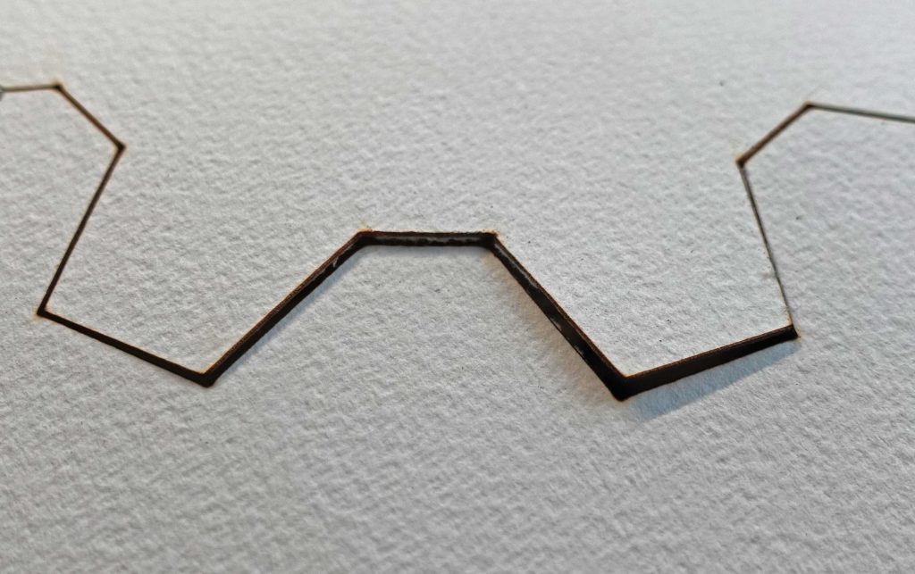
This also revealed how much out of alignment the beam was out, as the shrouds round mirrors (3d-printed in PLA) were melted in places. When I had previously installed the laser for testing, the alignment seemed pretty good but since then things have been dismantled and put back together again and more work is obviously needed!
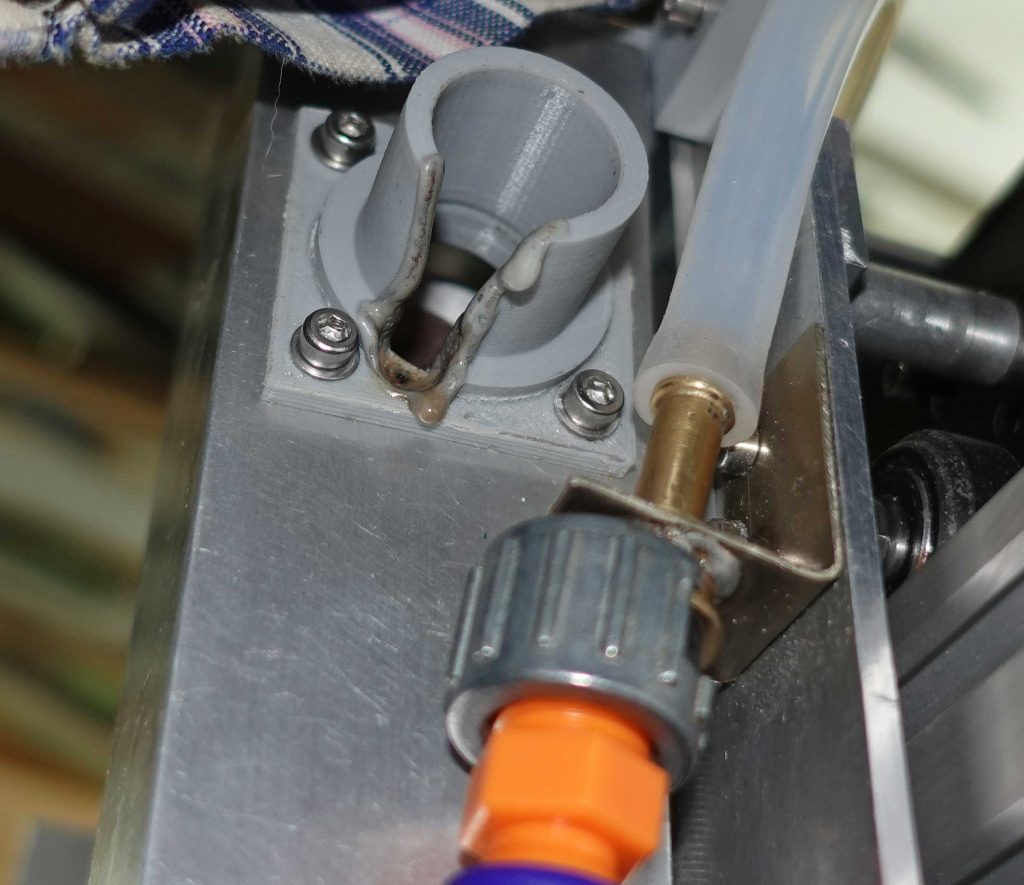
(Note to self!)
The picture above reminds me that I have recently noticed that the air blast nozzle needs to be moved to the other side of the lens/mirror assembly as, currently, it is hitting the framework at the far end of the Y travel before the limit switch is triggered.
Conclusions
Having thought a bit about it, I don’t think CO2 lasers give off significant RFI, so I tried testing without the kitchen foil. Everything still seemed to work OK. However, when I removed the foil round the Pi, the screen blanked from time to time (the program seemed to run but with no video). So it seems I should make up some better screening for the Pi.
My guess is that the RFI comes from the laser power supply. I assume inside the box are some big MOSFETS connected to a 10-times or more step-up transformer being driven by a square wave so lots of harmonics all through the radio spectrum being created. This is quite a cheap unit (relatively) – maybe more expensive ones are better protected. I thought there were regs about RFI emissions from electrical apparatus but perhaps these don’t apply to the Chinese. Of course, without the Chinese none of this would possibly be affordable so I can’t really criticise!
Foiling the RFI
The pictures show how I have lined the inside of the Pi’s case and lid with kitchen foil suck down with Gorilla Glue (this allows time to get the foil in position and burnish it flat). I apply the glue to the case in blobs rather than a continuous layer. Some 2 mm nuts and bolts through the case, when the glue has solidified, allows the shielding to be connected to ground with wires.
I have roughly realigned the laser/mirrors etc. Having got a very rough alignment with the laser level as previously described, I used 3-D printed “buttons” fitting over the mirrors to get the beam hitting the centre of the button as closely as possible by adjusting the mirrors. I use the timed pulse “feature” described previously. Two of the “buttons” (back and front) are shown below. 1.5 mm of PLA is just dented by the unfocussed beam at the laser current I am using. However, two hits in the same spot can blast a hole leaving a mess on the mirror (which I try to avoid!)
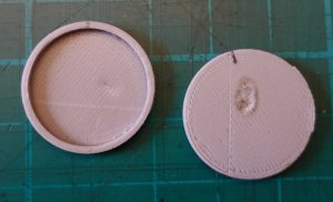
Safety first!
I use laser specs and a polycarbonate head shield at all times and keep the mirrors and anything which might reflect the beam out of view, by keeping my head down when firing the laser.
Now I can see the limitations of my home-made mirrors! It only takes a tiny fraction of a turn of the adjusting screws to move the beam a substantial amount. This probably leaves the alignment vulnerable to accidental displacement due to vibration etc. A solution would be screws with a finer pitch or making a setup which puts the adjusting screws further apart or both! (I also worry about the degree of polish on the mirrors – fine scratches must cause scattering and power loss – I will probably need to improve them in due course.)
Anyway, it’s time for some more testing. I am pleased that I am still able to cut out a complete “cog” in thick paper (after a few false starts) but better still, I was able to make a short test cut in 3.2 mm acrylic. The cut seemed to be about 0.13 mm wide with a laser current of about 10 mA. At this stage, I have not made any effort to optimise the focus of the beam so the cut could get finer or I might have been lucky with the focus. (I put a 2 mm piece of aluminium, as a gauge, on the surface of the work and raise the table until the probe stops it.)
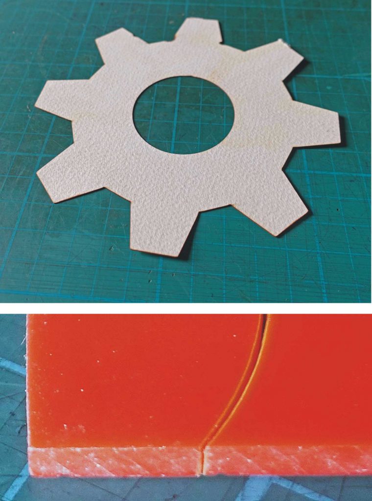
Power to the GCODE
Now I am going to try to get the gcode to switch the laser. First I have to set up laser mode in grbl. The spindle speed control which would normally be used in a CNC router or similar is co opted for laser control. The following values in the basic settings need to be changed:
$30=255 (maximum spindle speed), $31=0 (minimum spindle speed) and $32=1 (set laser mode)
As mentioned previously, the Z limit switch pin on the CNC Shield (which connects to D11 on the Uno) becomes the output to the laser intensity control on the HV PSU “IN”. With these setting there will be intensity steps from 0 (off) to 255 (maximum).
In gcode the commands M3 will turn on the laser and M5 will turn it off. S0 to S255 will set the intensity. The way it works is that the laser will only turn on if the laser is travelling across a cut (as a result of a G1 command etc.) If it is travelling to a new cutting location (G0 command), it will not fire.
M4 arms the laser but sets a mode which reduces the laser power when the feed is slowing down as when a corner is being negotiated. Presumably the S value and the feed rate need to be juggled to get the most of this mode – to avoid not having enough power to actually cut the corner, for example. I can’t remember any of this sort of thing being a concern when I was last using a laser cutter fifteen years or so ago!
For some reason the laser will still turn also on after a M2 or M30 (end of programme) so it would seem to be essential to include a M5 command at the end of a program. This feature does, however, enable the pwm output from Z pin / D11 to be tested easily. Connect a multimeter across the Z pins and enter the following command on the Arduino IDE’s Serial monitor for example: Unlock with $X then enter D2 then D3. Now enter values of S from S0 to S255. The multimeter should indicate values from 0 – about 5 volts.
Connecting it up with complications!
I want to retain the possibility to fire the laser manually so I need a way to switch between this and the CNC Shield pwm output from Z limit/D11. (By the way, on the Shield header, white is signal, black is ground – as you would expect.) I could just use a change-over switch but I can (as I usually do) make it more complicated than that!
New circuit…
I want the laser cutter to start off in manual mode when it is first powered up. A button push will switch it to program control (with a warning light turning on). Pressing the main stop button will change back to manual control (once the stop is reset).
I could use my old favourite, the 555 timer, to achieve this but, for the sake of variety, I’m going even further back to basics and using relays. One relay would do but it needs to be at least three pole (one to switch the grbl / manual control, one to turn on the laser and one to latch the relay. I didn’t have a three pole change over relay to hand so I used a couple of two pole versions. I used the spare relay pole to turn on the the warning LED mentioned above.
The relays take their power from the 15 volt motor supply, dropped down to 5 volts with a 7805 regulator. This means that they can be unlatched by hitting the master stop button. I couldn’t make up may mind whether to do it that way or just interrupt the main 5 volt supply with a switch button. This way saves a switch on the panel.warning LED mentioned above.
Taking the gate supply to the 2N7000 from the 5 volt supply from the laser psu prevents the blue laser warning LED coming on when the laser supply is disconnected by pressing the master stop. I ran the LED from the main 5 volt supply as I didn’t want to exceed the laser 5 volt current limit. I dunno why I used a MOSFET, a ZTX450 would have done the job!
The circuit is shown below. I decided to scrap the old strip board (Veroboard) version of the laser control circuit and include it in the new pcb which eliminates one mess (more to go, probably!)
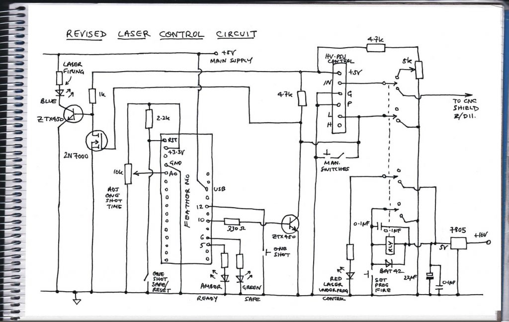
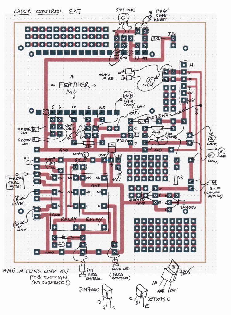
Above is the pcb layout. I managed to put all the tracks needed in bar one – which is about par for my particular course! The picture below shows the old and new layout. The “new” shows a mistake where I put a 3-pin header where a ZTX450 should be and vice-versa. Oh dear! Well at least it showed up in testing before I installed it (which is a pain because of the poor access I have “designed” into the project. Future lives etc.!)
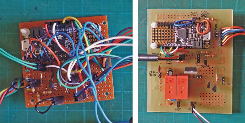
Feather or Pico?
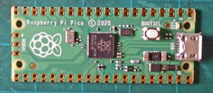
I toyed with the idea of replacing the Adafruit Feather M0 in the control circuit with the relatively new (at the time of writing) Raspberry Pi Pico. The Pico costs £3.60 whereas the Feather M0 Basic Proto costs £18.90. In this circuit they would be equivalent. However, I haven’t got to grips with the Pico yet and the Feather was already programmed and tested so I used it again. However, I do have high hopes for the Pico in future projects!
Testing times!
Back to the present! I fitted the new pcb into the laser cutter, put my coffee can lined with fire clay in front of the laser and carried out some tests. A couple of problems arose. Firstly, when in the manual control mode, the laser fired at a low current (unless the laser power pot was at zero). This is obviously highly undesirable not to mention very dangerous. I measured 2.5 volts at the laser psu “L” terminal. This is pulled to the 5 volt supply by the 4.7k ZTX450 collector resistor (the ZTX450 should be off and the 2N7000, being a mosfet, has no effect). I would have guessed the “L” terminal would have been tied to 5 volts by a pull up so even if I had forgotten to solder in the 4.7k resistor, it should have still been high, switching the HV off. I tried connecting a 2.2k resistor between the “L” and 5 volt terminals on the psu connector and the problem went away. I’ll have to check the pcb for faults in due course.
The second problem involved the power setting pot which fails if the spindle is pushed sideways. I’ll replace this with a pot which costs more than a pound. I guess you get what you pay for!
Calibrating times…
Having got these problems out of the way (sort of) I tried calibrating the gcode S value against the laser current. I loaded the Arduino IDE on the Pi and opened the Serial Monitor. $X unlocks then (it seems) M2 or M30 (end of program) need to be input. Then S0 to make sure the laser is off when M3 (turns the laser on) is input. Then I input various values of S up to S150 and noted the laser current. I plotted these on a graph. I would imagine I didn’t measure a couple of currents too accurately as they don’t lie on what seems to be a line (or at least a simple curve) but this exercise is just to get a rough idea of what is going on and to check that the laser is doing more or less what it’s supposed to do.

Next: I’m getting tired of cutting the same old gear shape. It’s time I dried designing something new!
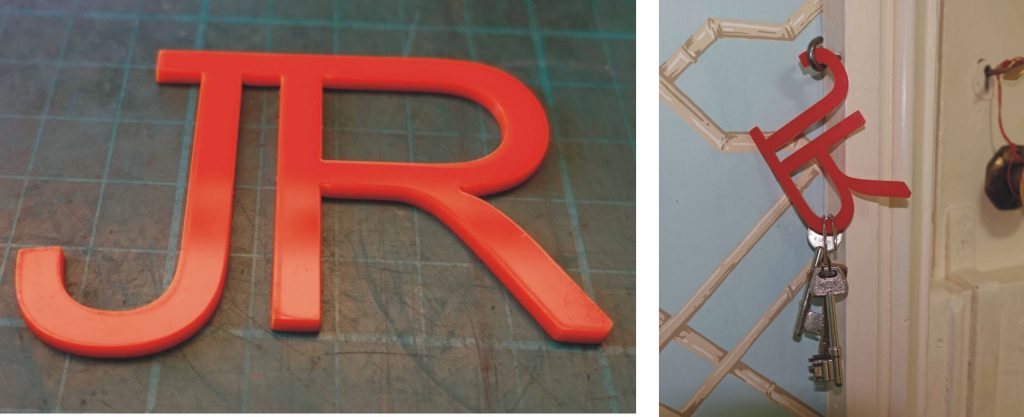
Well it’s not exactly an earth shattering piece of design in 3 mm acrylic but it allowed me to remember how I was getting these shapes into GCODE. Design in Corel Draw, import into Inkscape as a .cdr file, add a layer, then click on Object to Path, finally in Gcodetools, Path to gcode accepting all defaults. Then I opened the GCODE in Notepad and deleted the repeated paths and all commands involving the Z-axis (when I get to grips with the defaults in Gcodetools, I may not need to do this! NB. You have to “apply” the defaults in all the menus before a large dark-shaded notification appears and at that point the GCODE is written to file.)
Finally, I added S80 in the header to define the laser current to be used (about 10 mA – I’m not sure whether there is a linear relationship between the power and the current but at present, I am assuming that this corresponds to about half power). At the end I added S0 to reduce the current to zero to be on the safe side.
Different materials…
So now I tested the laser on a few materials. I tried to get the best focus by testing at a range of distances between the lens and the material. At 20 mA it cut through 5.5mm plywood and 10 mm softwood. It also got through some 6.5mm MDF but just engraved a piece of Tufnol (which, I suppose, might be useful for labelling control panels etc.)
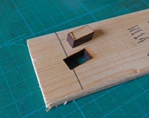
I could, perhaps, reduce, the feed rate to get a deeper cut. The default from Gcodetools on Inkscape is 400mm per minute. (I did a rough measurement with a ruler and my wrist watch which came out at about 380mm per minute, about 6mm a second – perhaps I need to check the GRBL calibration? However, the dimensions of things cut are pretty accurate, allowing for the width of cut.) I reduced the feed to 200 mm per minute and that made a slight improvement in depth of cut but not as much as I had expected.
The results of my cutting tests seem to correspond with what folks on the web say they would expect from a (nominal) 60 Watt laser. Overall, however, I felt it might cut a bit more powerfully. I have resisted the temptation to up the current above 20 mA. The pwm driving the power supply was set at 150 out of 255 so there would be plenty of scope for upping the ante. However, the dire warnings on the web about seriously shortening the laser life have given me pause!
My guess is that my mirrors could be improved. With a lens you can see scratches which must cause scattering and therefore, loss of power at the sharp end. I will try to polish them more effectively. Perhaps, I will end up buying a set, eventually.
Novel nozzle
The air blast nozzle was giving some trouble. It was too big, too difficult to position and the nozzle bore too large to produce a fast blast of air. In particular somehow the thing had somehow encountered the beam and melted! I have replaced it with a piece of 5 mm brake pipe with the end squeezed flat in a vice to produce a narrow rectangular nozzle.
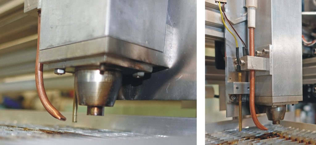
Below: The old nozzle, before and after… whoops!
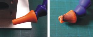
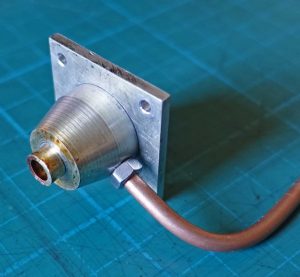
RFI reprise
Just to return to the (alleged) RFI causing false hard stop errors during cutting. These still happen from time to time. My latest wheeze is to reduce the impedance of the Arduino pins connected to the limit switches by tying them to 5 volts with 2.7k resistors and screening some of my cable conduits with copper tape (to which it is possible to solder wires for connection to ground).
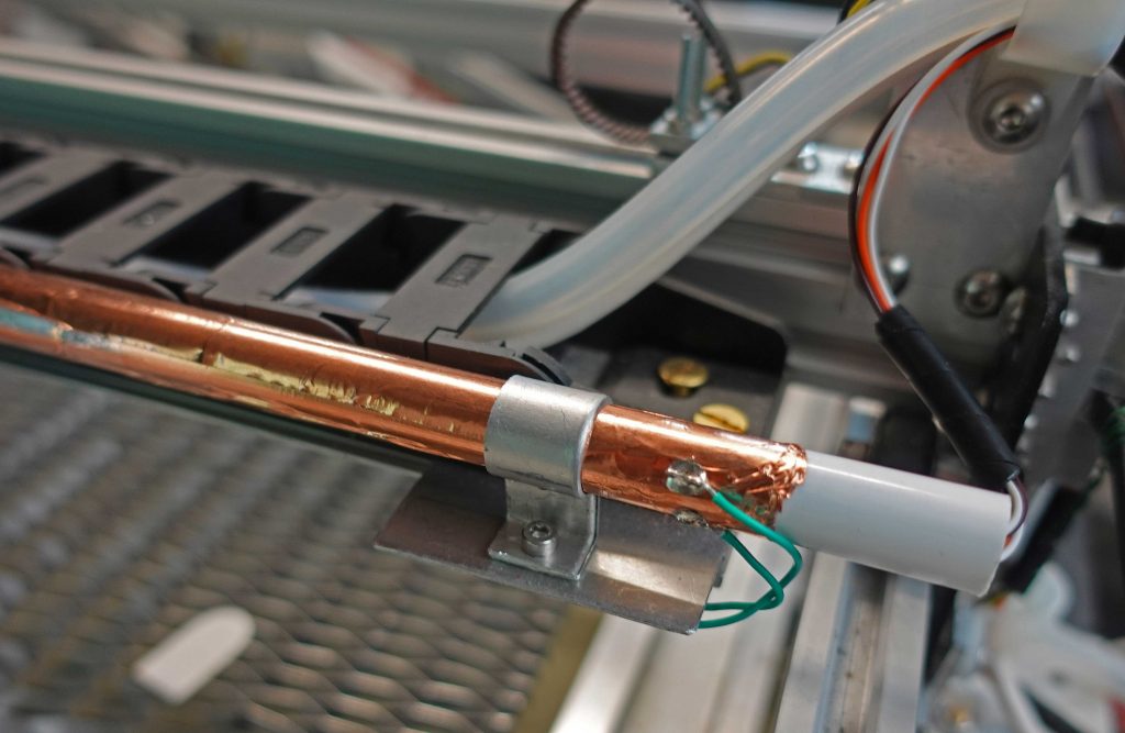
Time will tell whether these actions will finally solve the problem. I now guess that it would have been better to have set up the limits to be closed until broken by contact rather than open till closed by contact. Then the inputs would have been (almost?) immune to RFI. Live and learn!
Update…
This shielding etc. does seem to have solved the problem – fingers crossed! However, shielding means the internal Pi WiFi does not work. I had to resort to a usb unit with a nice big antenna. After dangling this out of the workshop door supported on a hook for some time, I eventually drilled a hole in the wall and sealed the dongle in a piece of 25mm water pipe (with 3d-printed caps) together with some silica gel and clamped it to the wall.
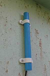
Extraction system
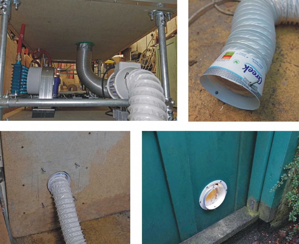
I completed the extraction system with a cheap 100mm in-line extractor fan (the sort you put in the loft to ventilate the bathroom). I had a piece of flexible pipe left over from an old tumble drier installation and, once I had removed most of the ingrained fluff, used it to connect between the laser cutter base and the fan. I 3D printed a spigot to help with connection but it wasn’t quite the right size so rather that making it again, I used some Gorilla tape (I’m getting a bit slapdash!)
At the outlet end of the fan, I used some light weight spiral reinforced polythene pipe and shoved it through a hole in the door I made for the purpose. I can bolt a piece of wood over the hole when it’s not in use. The tube is terminated with a cut down Aldi yogurt pot which stops the pipe easily slipping out of the hole in the door when it’s opened and closed.
Another case to be solved
Now for some sort of case. Since I will probably need to fiddle with the workings (indefinitely!) the case needs to have easily removable panels. The material for the side panels needs to be decided. I think I favour clear polycarbonate. This would enable me to see what’s going on and protect from reflected infra red scatter. I will try to obscure any view of the surface of any of the mirrors with opaque material although polycarbonate should stop a direct beam for a moment or so.
I can’t see how a direct beam could escape (other than by a serious mechanical failure of a mirror mount) but should it do so, the burning of the polycarbonate would give warning of impending disaster (fingers crossed!) As a general policy, I will continue to wear laser specs at all times in the vicinity of the machine.
I am leaning towards aluminium angle on the corners and the top in the form of a lift off-lid. I also want to leave a “notch” in the corner so the keyboard and monitor wont stick out too much. All in all, I am beginning to believe, this might turn out to be the most difficult part of the build!
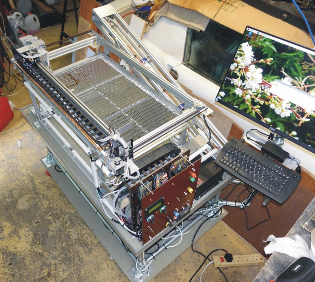
Above: Just needs a case?! (Also someone needs to restore that Porsche 914 sitting alongside!)
Engraving diversion
I’ve been diverted into trying some laser engraving. I’ve found LaserGRBL a great (free!) program which is a GCODE sender and can also generate GCODE from a number of sources including jpegs etc. Although there isn’t a version for the Raspberry Pi, you can generate and save the GCODE on your Windows PC then transfer it the Pi and load it onto bCNC to output to grbl. This seems to be a much better option than Gcodetools in Inkscape (which, to be fair, is really designed for CNC routers etc., I think.)
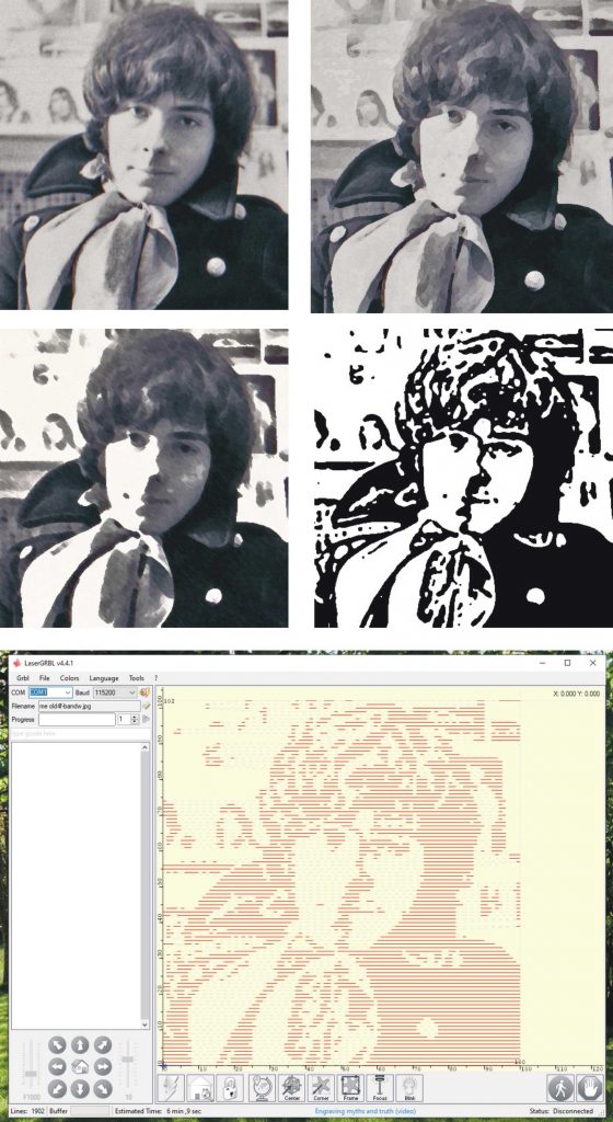
I took a very old picture of yours truly (1969 omg!) and processed it with Photoshop till it was a blocky monochrome (looking a bit Picasso-esque I thought!) Then I opened it in LaserGRBL. A dialogue box appears which enables you to chose various types of conversion. I chose 1bit BW Dithering at one line per mm. (There are more possibilities within this selection which seem to reflect different algorithms for achieving the effect.) This 100 x 100mm approx cut took about ten minutes. Setting more lines per mm (say, two) means the laser lines appear to merge which will give a solid block effect rather than a raster effect.
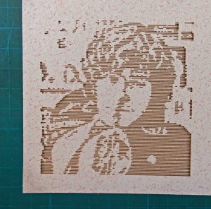
The material I used was some white-faced mdf from the backs of some old kitchen cabinets (waste not, want not!). I used an S value of 25 (out of 160 max allowable current) and a feed rate of 1000mm / minute. At the end of the cut I washed the soot out of the grooves. Here is another engraving (of my grandson!) using two lines per mm which gives a more photographic effect as mentioned above.
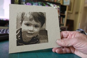
Recap on image creation
So my design process for laser cutting/engraving seems to be as follows: for cutting lines, design on Corel Draw9 (it’s what I am most familiar with), save then open in Inkscape, scale by 133.333%* (or, easier, copy in CorelDraw and paste into Inkscape – no scaling required!) and save as svg, then open in LaserGRBL, set feed and max power required, create GCODE and save. Next, copy to the laser Raspberry Pi and load into bCNC to send the GCODE to the machine itself. Phew!!
(* It seems that Corel Draw cdr files come out smaller when opened in Inkscape – a 100 x 100 square appears to be 75 x 75 mm and so needs to be scaled by a factor of 4/3 or 133.333%. As I said previously, I have heard this is something about a confusion in Inkscape between mm and pixels.)
For raster type engraving (I don’t think this would ever involve cutting except, perhaps, in paper or similar) it seems you work from a jpeg (or equivalent). First, however, the jpeg will probably need to be processed in Photoshop or the free Gimp which is very powerful. I think the idea would be to simplify the image, increase the contrast or use special effects to make the image more suited to engraving with the laser. It will need to be resized to meet whatever your requirements are. I find Corel Draw 9 to be great at this. Load the image, set guides and drag the image to fit. Then export as a jpeg and just open it in LaserGRBL. LaserGRBL enables you to set the size of the image which will be engraved regardless of its original size (although, this must affect the definition, I guess). Use the offset facility to position it where you want. There are a number of adjustments which will alter the type of effect that will be rendered which I might go into later when I have had more time to get used to them. However, I can say now that the number of lines per mm in the raster is very significant in how the finished engraving will look. Currently, I am using two lines per mm.
Focus pocus!
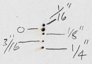
Next, I tried a bit more focussing. I used my “one shot feature” (see above) to pulse the laser at a controlled current for a controlled period of time using a piece of “back of an old cabinet particle board” as a target. I used five different focus distanced relative to the probe on the lens unit. These are in Imperial as I use pieces of aluminium bar as shims. As you can see, the hole and the scorched area gets smaller up to 3/16” and increases at 1/4”. So the best focus is about 3/16” relative to my probe. I could probably refine this later.
Multiple passes
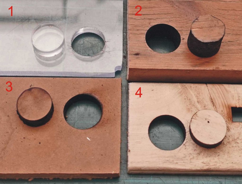
Finally in this segment, I did some experimenting with multiple passes of the laser to see how that affected depth of cut. In the picture number 1 shows a cut through 8mm acrylic which required two passes but left a very nice clean cut. Number 2 shows how it took six passes to just about get through 19mm pine. The hole was very charred and not satisfactory. Number 3, 10mm MDF, needed four passes and the result was fair. Number 4 was through 10mm softwood which only needed one pass.
I experimented with altering the focus (moving the material nearer the laser) to see if this would reduce the number of passes but the improvement was marginal. There seems to be a law of diminishing returns operating here – the greater the pass number, the smaller the depth of cut with each succeeding pass. This is to expected as a lot of the energy get dissipated in the existing cut burning away and hollowing out the walls. A solution would be to cut from both sides but that would require very careful alignment.
Back to the case
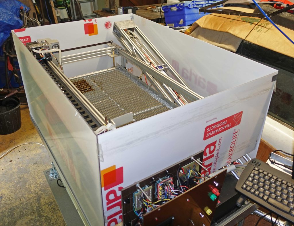
I decided to use 3 mm clear polycarbonate rather than acrylic as the consensus seems to be that its effectiveness against infrared is greater. Also polycarbonate is more resistant to shattering. In the picture above I am trying the pieces for size in the slots round the base.
Aluminium angle at the corners will keep the bits together. I am making sure the case is easy to demount so that I can do maintenance, retrieve bits that fall through the honeycomb etc. etc. In particular it will be possible to slide out the front after undoing just a couple of screws. At present, I am proposing that the top will be a plain piece of unframed polycarbonate (except for, perhaps, a couple of handles) which will simply rest in a recess in the top frame of the case. Its weight will hold down a micro-switch connected to the master stop circuit.
I might consider a hinge system for the top in the future. One question is whether the lid will sag too much without reinforcement.
Another question is whether I will need inlet vents to allow enough airflow through the case for the extract fan to efficiently remove fumes or whether there are enough gaps in the construction to render this unnecessary.
Constructing the case
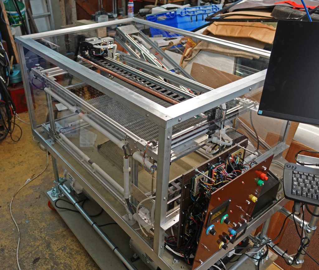
I’ve made the case from 3mm polycarbonate as mentioned above and made the frame from aluminium angle, 1x1x1/8 inch and 2x1x1/8 inch. As you can see from the detail of the corner, I have sandwiched the polycarbonate between the angle screwed together with M5 screws. I’ve trimmed the angle to come together at the corners giving as clean an effect as possible.
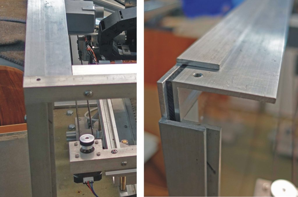
Above: The inner and outer vertical angles (which are made from the 1×1 inch angle) are fixed to the (small) side panels by the M5 screws tapped into the inner angle forming slots into which the (large) front and back panels can slide. The top is made from a sandwich of 1×1 angle on top with 2×1 angle under forming the recess on which the lid will sit. The front and back “top” angles oversail the side angles so they can be locked together with more M5 screws.
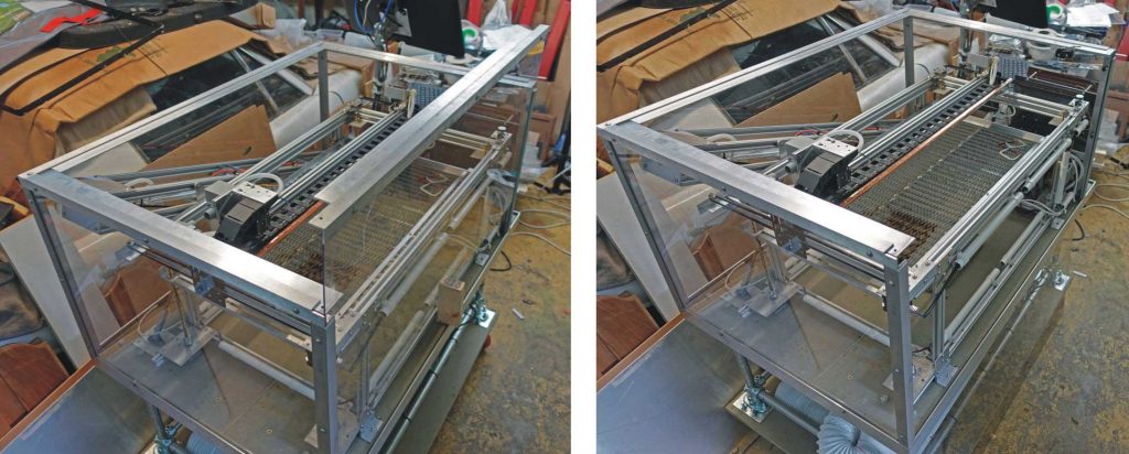
Fuming
With regard to the fume extraction from the case, I mentioned above that I was not sure whether I would need inlet vents. After a trial with the lid on, it was clear that if I wanted to clear the fumes, I would need some way for air to get in as well as out! So I fitted some cheap aluminium louvres (from Screwfix) over holes in the sides of the case (see picture below).
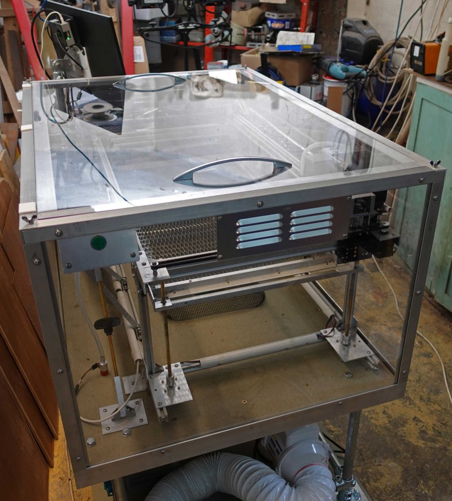
In the picture above you can also see the lid with handles and some pieces of white Teflon (on the left) which enable the lid to be slid back without the aluminium frame scratching the polycarbonate (it may be very strong but it scratches so easily!)
Glad this bit’s over!
I have to say this part of the project is the most irritating! It involves cutting, quite accurately, 16 pieces of angle and drilling about 50 holes in more or less the right place. I need to organise a chop saw or similar for angle, tube and bar etc. As it is, I end up hack-sawing the angle over size, then trimming it on the band-saw, then finishing it on a sanding disc! Then there are the cut outs that have to be done on the band-saw and then filed to size for the corners. Tedious! (I still need to make a case to fit round the electronics / controls etc.)
Keeping it safe…
Next, I have to incorporate a safety switch which will cut out the laser if the lid is not in place. I have a very nice ancient micro switch lined up for this. (I bought a few of these from my favourite army surplus store – “Athur Sallis” in Brighton – probably more than 40 years ago!) There will also be a switch to bypass the switch for when I need to move the gantry without the laser firing and the lid off. (It would also enable the laser to fire with the lid off but not accidentally, given the way my switching works – I hope!)
Nostalgia wallow!
By the way, back in the day, you could get some wonderful stuff at army surplus stores. Arthur Sallis, for example, had transmitters and receivers from Lancaster Bombers. I was given a transmitter to play with (I was about eleven at the time). Unfortunately, I dismantled it and I don’t think I have even the smallest part left now. (The same thing is true of an Edison Phonograph my grand parents gave me which I very much regret now!)
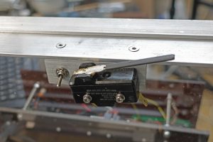
Laser vs. Polycarbonate – (Poly had better win!)
Now to test the efficacy of 3mm polycarbonate at stopping laser radiation. I fired the laser at a piece of the material under various conditions with a piece of paper behind to detect what got through, if anything.
All tests were at a current of 20mA. First I fired the laser at the polycarbonate at the optimum focus distance with the paper separated by 6mm from the bottom of the plastic. I tried about one second and five seconds. The laser made a mess of the plastic but did not make a physical hole. The paper, however burnt through. I guess this is secondary radiation from the hot polycarbonate. The paper still burnt through when separated by 45mm.
Hopefully, there are no circumstances where my (or anyone else’s) eyeball will be in a similar position to the paper but it still gives a warning about how potentially dangerous lasers are.
A more realistic (I hope) test followed. I set the polycarbonate 24mm beyond the best focus so the beam was diverging. The beam made a mess of the plastic but the paper, 45mm away, was unmarked.
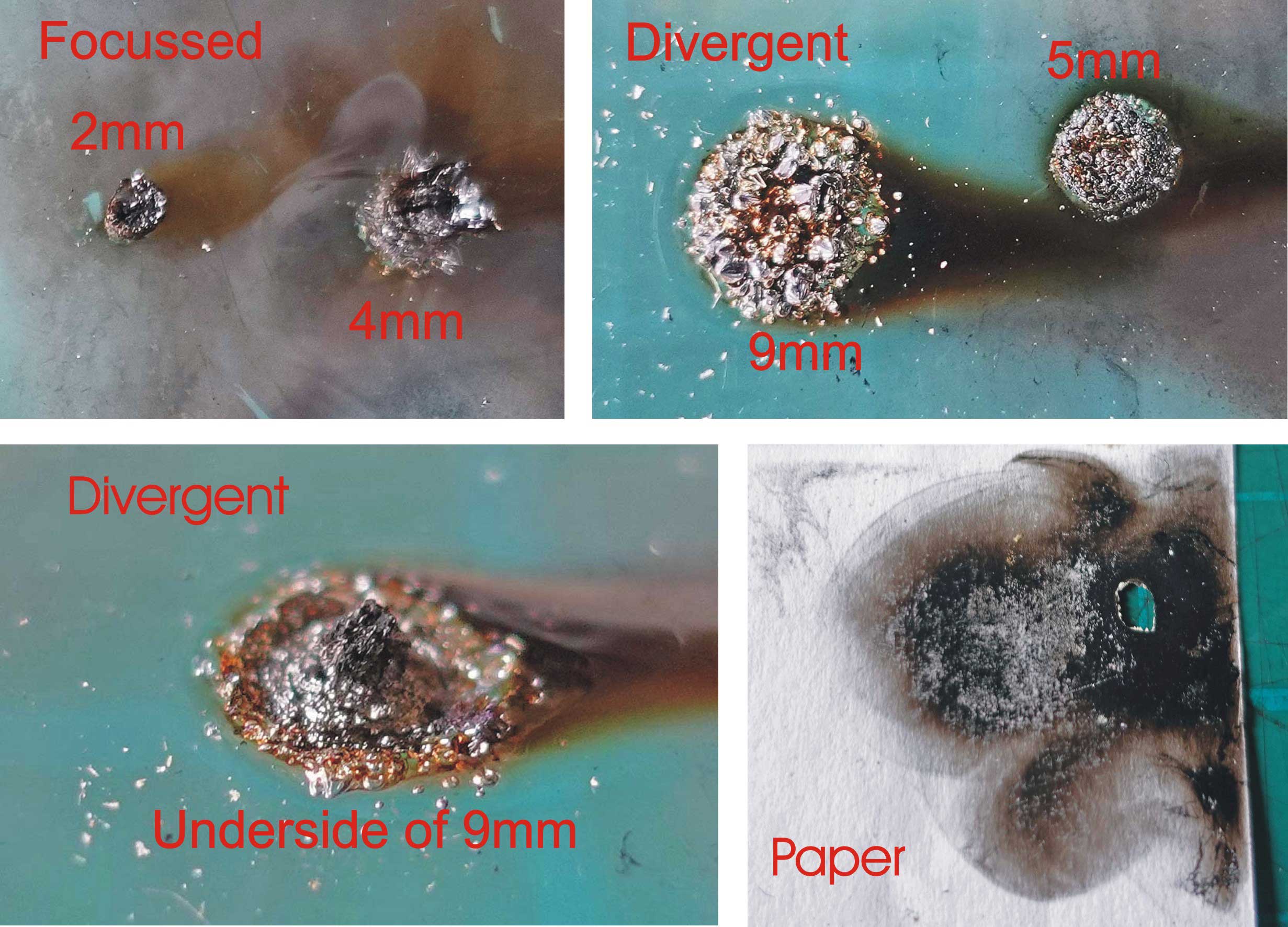
Re the pictures above: the hole in paper was mostly much bigger but I chose this one because of the interesting scorch/soot marks. (The green colour is top of my desk coming through, of course.)

Above: This is the effect of the unfocussed beam (direct from the laser) on the polycarbonate for about one second. The diameter of the mark is about 7mm. The interesting thing is that the rear of the plastic sample is still smooth and polished (right hand picture – a bit difficult to see) so there has been no penetration.
In conclusion, I suppose I am confident the polycarbonate will screen out any scatter or indeed divergent direct beams or direct unfocussed beams which could result from the layout of the laser cutter. Nevertheless, I’ll still always wear laser specs when working with the machine.
Another mod…
Here is another “improvement” (complication!) It’s irritating to have the extraction and particularly the air assist compressor running all the time. I can switch them off but then I forget to turn them on when the laser is running which isn’t good. I intend to switch these two bits of equipment on automatically when the laser is activated. All it will take is a relay linked to the laser firing circuit. I’ll put the relay in an ordinary 44 mm deep box with twin gang sockets and a lead to the main power distribution.
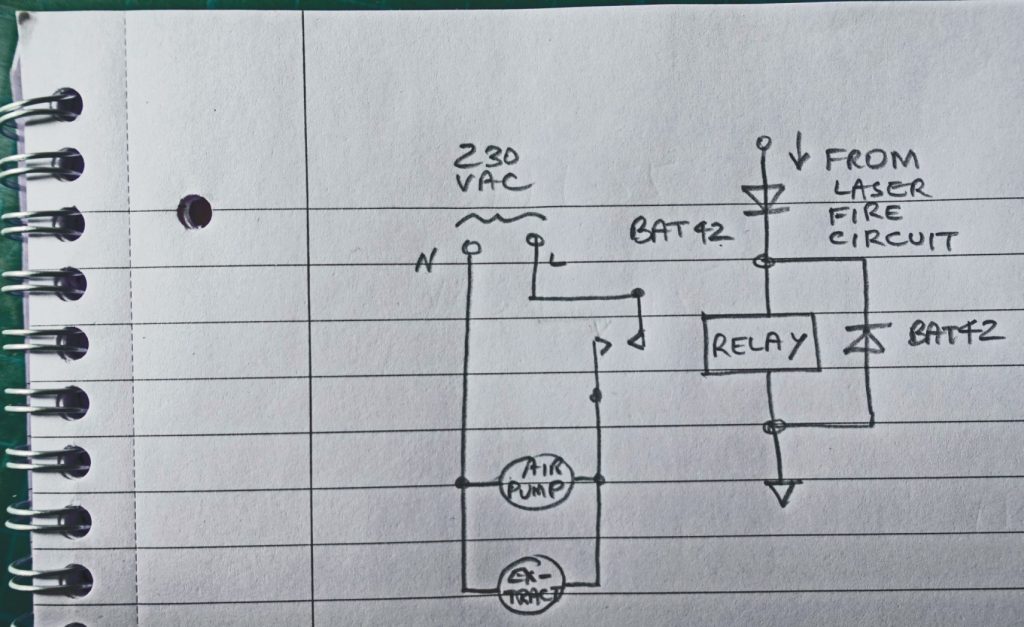
The circuit has a diode across the coil to suppress reverse voltage spikes when the relay is turned off and a diode in the supply to the coil to prevent a short circuit if it is connected the wrong way round. The relay is NAIS ALE15B05, a type I frequently use to switch 230vac. It doesn’t seem to be manufactured any more so I have to rely on Ebay NOS if I want any more. I suppose I’ll have to graduate to solid state relays in the end (don’t trust them!)
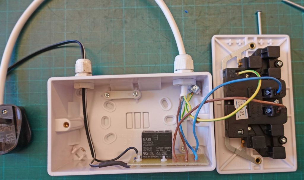
Digital to analogue (/digital)
Another improvement will convert the pwm, digital drive to the laser to analogue/digital drive. I believe all this will only involve a potentiometer gain control between the GRBL D11 output and a toggle switch to select digital only and analogue/digital. I imagine this will enable me to fine tune the output for low power engraving etc. I’d like to fit these controls on the main panel which, as I have already pointed out, is already crowded! I hope it will be possible.
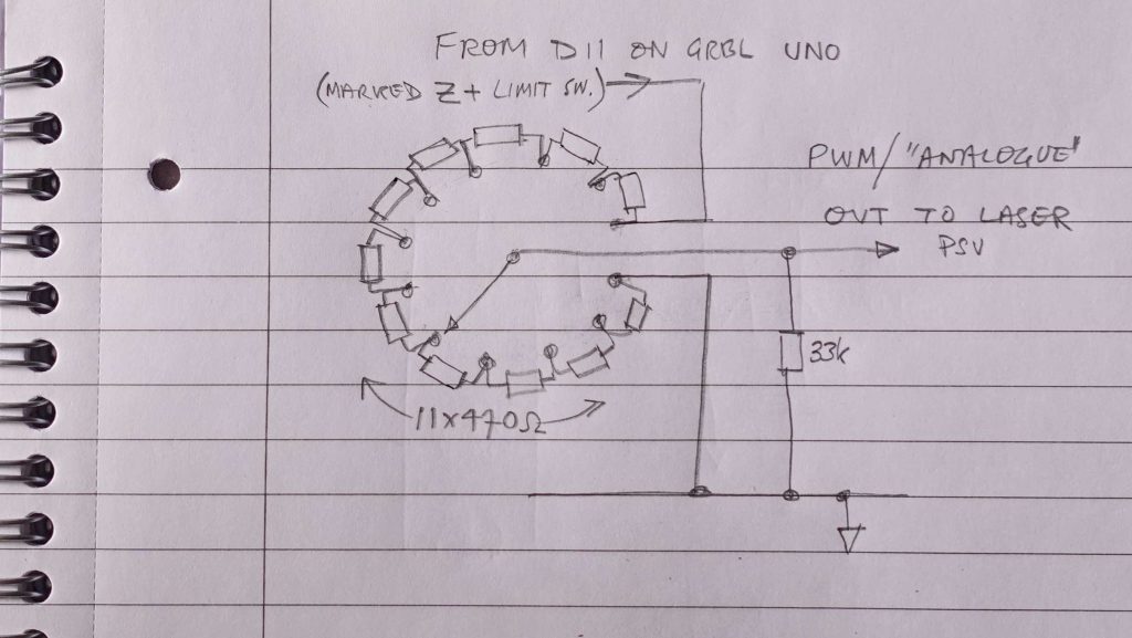
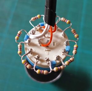
In the end, I have opted to make a potentiometer using fixed resistors and a rotary switch (see pictures above). The reason for choosing this method over a conventional rotary potentiometer is that it offers better reliability, ease of selecting desired values and resistance to getting accidentally knocked to a different value to the one set (perhaps during a run).
The switch is break before make so the “output” would float momentarily if the switch were to be turned during laser operation (although it’s unlikely that I would want to do that?) So I have included the 33k resistor which will make the laser output zero during the momentary break which would seem to be for the best.
Now I need to calibrate the switch position against laser current at, say, S140 or 150 (which is the safe maximum for this laser, I think) and also at a much lower level, S25 – see plots below.
Laser current plots
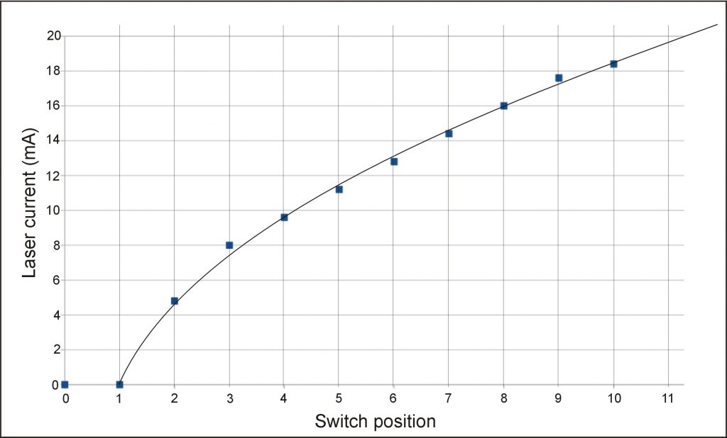
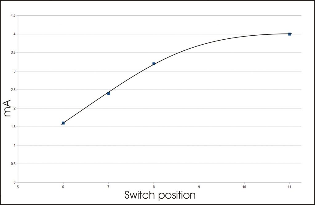

(The plot above is with the switch effectively at maximum – I made the plot before I installed the switch!)
Perhaps it would be useful to calibrate the current with more S values but I think I’ll leave it at that for now.
Overall, the “analogue” adjustment seems like it could be very convenient for determining the best current for a particular job. For example, I was investigating a good value for engraving acrylic and, having set S75 which is sufficient to cut 3mm acrylic, I was able to fiddle with the adjustment and found position 3 suitable (about 3.5mA). This is just about the lowest current which can be registered at S75. However, at S25 and switch position 6, I got an indicated 1.6 mA which is the lowest current I have obtained so far.
I don’t know whether this is a function of the HV power supply or the laser tube itself. There must be a minimum input energy to initiate the various quantum interactions which are responsible for the laser’s operation. I might have had a chance getting some sort of handle on this many years ago when I studied physics at university but now brain fade is too far along the line! Anyway, I was at college so long ago that at the time, lasers had only recently been invented and they were not in the syllabus.
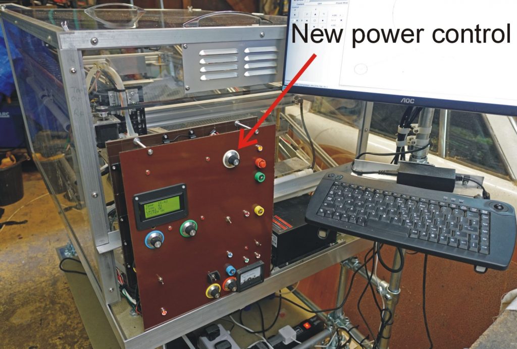
Above: The (I hope!) completed control panel other than some labelling. There seem to be a lot of buttons, toggle switches and potentiometers (16)! Perhaps I would rationalise if I ever were to make a mark 2, but right now they all seem useful (if not essential).
As I have mentioned before, a mark 2 version would package the electronics in a more accessible way which would result in the controls being presented differently. Perhaps I could have implemented the controls graphically on a window on the Pi. However, for reliability and, more importantly, for safety, I think it’s important to have controls like the master/emergency stop, the master reset and the laser enable buttons connected to the circuitry in the simplest and most basic way. It probably isn’t a good idea to be able to fire up the laser remotely via VNC!
Laser pointer accessory
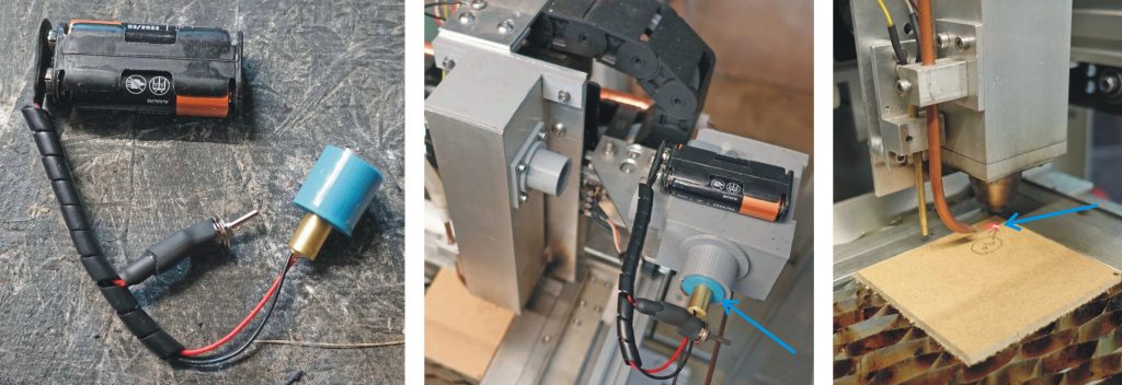
Pictures above: Here is another accessory in the form of a laser diode / pointer to give an idea of where the CO2 laser beam will strike the work. I have connected a cheap laser diode unit to a switch and a 2xAA battery holder. I 3D-printed an adapter to enable the led unit to slide into the shroud over the second mirror. The result is a little vague as the pointer beam is not that crisp and at normal focus distance for the CO2 laser, the spot on the work is about 2.5mm in diameter. Perhaps I should experiment with different focus distances as red light is not going to focus at the same point as infra red?
More trials converting jpegs to GCODE
More trials converting graphics to lines (vector graphics) that can be engraved or cut by tracing. I found a nice Chinese dragon two-colour jpeg on the web and cleaned it up a bit with Photoshop. A high contrast image like this should be easy to trace.
My first attempt involved using the trace facility on Inkscape. The image traced accurately and the resulting .svg file loaded into LaserGRBL and produced a GCODE file. However, this didn’t work with bCNC, part of the drawing was missing. My conclusion is that the traced .svg file was too complex and the file displayed on Inkscape showed a lot of nodes.
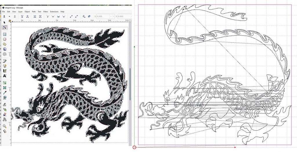
Next, I tried manually tracing the original dragon jpeg on my ancient CorelDraw program. This quite time consuming but produced a vector graphic with about half the nodes of the Inkscape trace. I had to load this into Inkscape in order to convert it to an .svg file that the other programs can use. This worked in LaserGRBL and bCNC and produced a nice engraving on a piece of white-faced particle board (the back of some old kitchen cabinets).
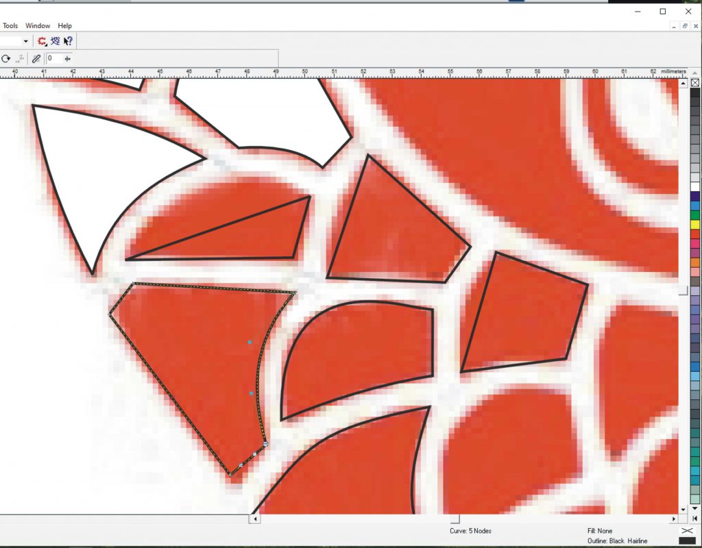
Above: Tracing manually involves drawing straight lines (Bezier mode) round the shapes in the jpeg, coverting the straight lines to curves, then moving the “handles” associated with each node to get the right curve to accurately outline the shape.
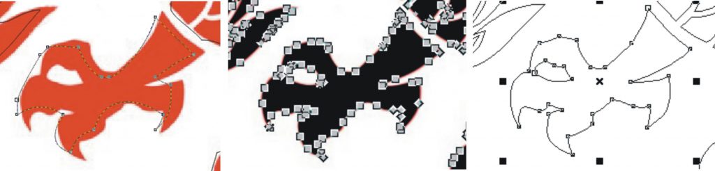
Above: Left, an attempt to use the Corel Draw trace function (unsuccessful, obviously!) Centre, about 65 nodes on this part of the drawing using Inkscape (but a good fit to the original). Right, about 31 nodes with manual tracing.
Finally I tried the “Vectorise” trace option in LaserGRBL. It needs a bit of fiddling with the contrast settings but, rather to my surprise, produced an excellent trace and the GCODE file fed perfectly into bCNC. All with very little effort!
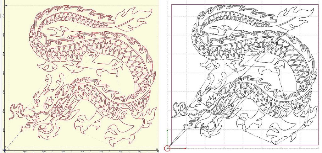
Above: Left, the vector graphic produced by LaserGRBL and right, it works very well when the GCODE is loaded into bCNC to output to the laser cutter.

Above: The test engraving. Settings: speed, 1000mm per minute at S = 25 which equates to about 2.5mA tube current.
However, if you want to incorporate the graphic into a wider piece of design work (such as a decorative border) it would seem easier to use the “hand made” tracing in the design. The tracing made by LaserGRBL can’t be extracted as, say, an .svg file (I assume it just exists as GCODE). You could append GCODE for the decorative border to the GCODE trace but it would be tricky to ensure that the trace was correctly placed.
Once upon a time a long time ago…
An example is my current attempt to complete a project I started a very many years ago! (I took this item to an interview to my very first job as an example of what I could do.) The project is a Chinese style cabinet that has been waiting for decorative panels on its doors all these years.
I intend to cut these panels in white acrylic and fill the engraving with colour.
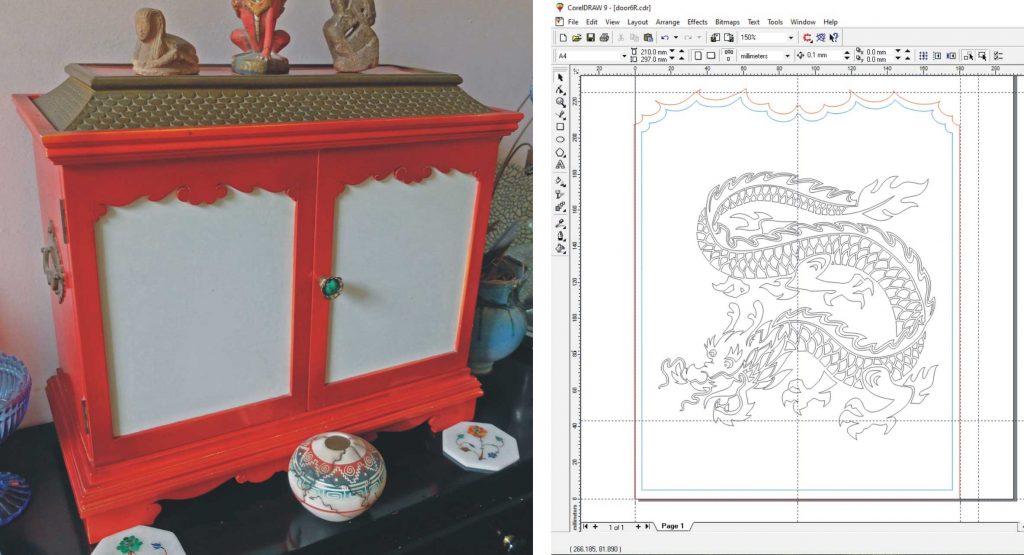
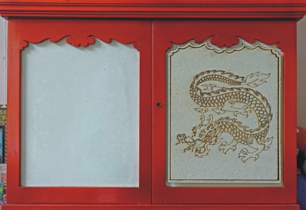
Making connections or not!
I had a sudden problem as I was test engraving the dragon. I got some jiggly lines where they should have been straight and gradual displacement of the design. I observed that one of the gantry motors was not functioning so the gantry moves in jerks and also loses position. At first I suspected the Polulu driver but soon it became clear that the connector to the driver module was hot and on removal was partially melted. This was caused by one of the four female connectors not being fully inserted into the plastic body resulting in poor connection with the header on the Pololu module.

This was my fault as I had made up this particular connector! The problem is that I am too mean (and uncertain about whether the kit I might buy would be any good) to pay a considerable amount of money for a crimper for these Dupont-style connectors. (What appears to be a very good account of how it should be done can be found at: www.mattmillman.com/info/crimpconnectors/dupont-and-dupont-connectors/)
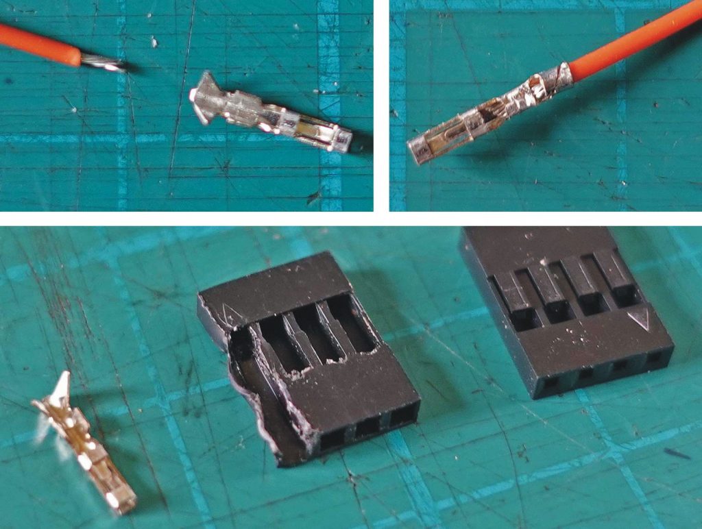
I’m afraid I use a combination of small side cutters and small pointed nose pliers to crimp these. It produces electrically and mechanically satisfactory crimps (in my opinion!) although, perhaps, not aesthetically perfect (see picture above). The problem is that sometimes the rear part of the connector becomes slightly bent and does not fully engage with the plastic body. It can easily be straightened out but only if I notice it has happened!
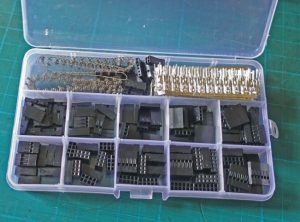
There are a great many Du Pont style connectors in this project. This is partly a function of the way I have built it in modules (which in turn is a function of my developing the project as I went along). I guess they have a potential for unreliability – not least because they can be easily pulled apart. I have taken to taping together in-line cable connections for this reason.
Case complete – well not quite
The completion of the case will require four sections to go round the various bits still exposed. The construction is mainly 1.2mm aluminium sheet bent and folded as required. As with the main sections of the case, it slots into the groove formed round the edge of the base.
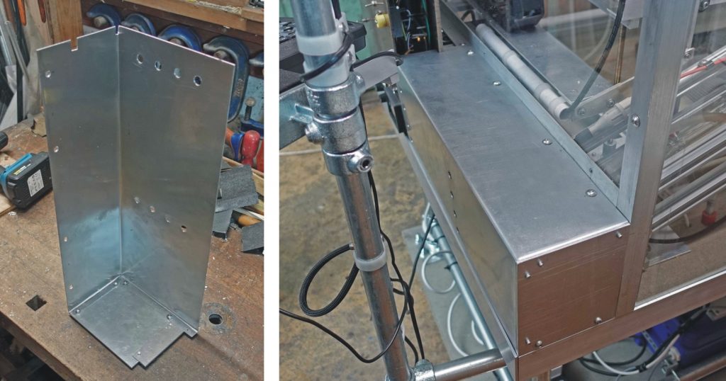
This is all a bit fiddly because I never had a well thought out design at the start of the project. The obvious overall concept might have been a box with a sort of bevel at the front which would have the controls on it.
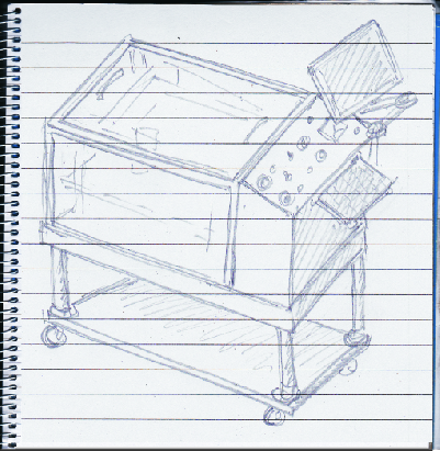
Anyway, the design it as you go along method has led to some advantages. For example, with the electronics and controls where they are, you get a much better view from the side of what is going on in the laser cutter.
My excuse: easier with the right kit!
Incidentally, in the absence of any kit specifically designed to fold sheet metal (metalworking brake) I tend to make such boxes as little as possible! You can clamp the metal in a large vice or on the edge of a bench and bend the metal with a stout piece of wood and some elbow grease. However, if the metal has much resistance to bending, your edge will not be sharp and will require some hammering which can lead to imperfections.
If you are using thin aluminium and the result does not need great strength, A short cut is to score the sheet down the score line a few times with a Stanley Knife. When you bend the metal, the score weakens it so that it bends much more sharply and with much less effort.
Cut to the chase
This is also how I cut a thin sheet of aluminium. Score it about ten times with a knife, bend it a small angle and bend it back, repeating until the metal breaks. Easy!
Difficult bit…
The most difficult part of this sheet metal work is boxing in round the top of the electronics/control panel unit. Try as I might, errors have crept in in the underlying construction leading to the unit not being quite square. You don’t notice it by eye (unless you are not wearing varifocal glasses – with these, everything looks normal and your brain makes everything square it expects to be square but it is acting on misleading information from the eyes!) However, when trying to make something that fits tolerably well, it can be awkward.
The first thing to do is make a pattern out of thick paper. I made it in two parts which I bent into “L” shapes, marked the overlap, and glued them together (contact adhesive) allowing an extra mm or two for tolerance. I scored the folds to get a clean bend.
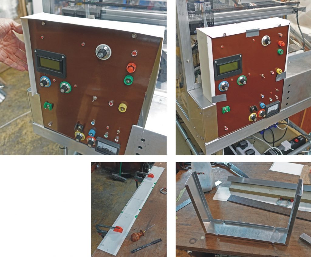
Above, left: I taped the paper at the bottom to the base and drew where the front and rear panels met the paper. Above, right: Having bent the “tabs” on the pattern, I tried them for size. Bottom, left: I clamped the pattern onto the aluminium to mark it out. I used an awl to mark through the pattern where the folds were needed. Bottom, right: The case/cover with all its bends. I bent the side tabs in a vice with the jaws extended with a couple of bits of heavy angle.
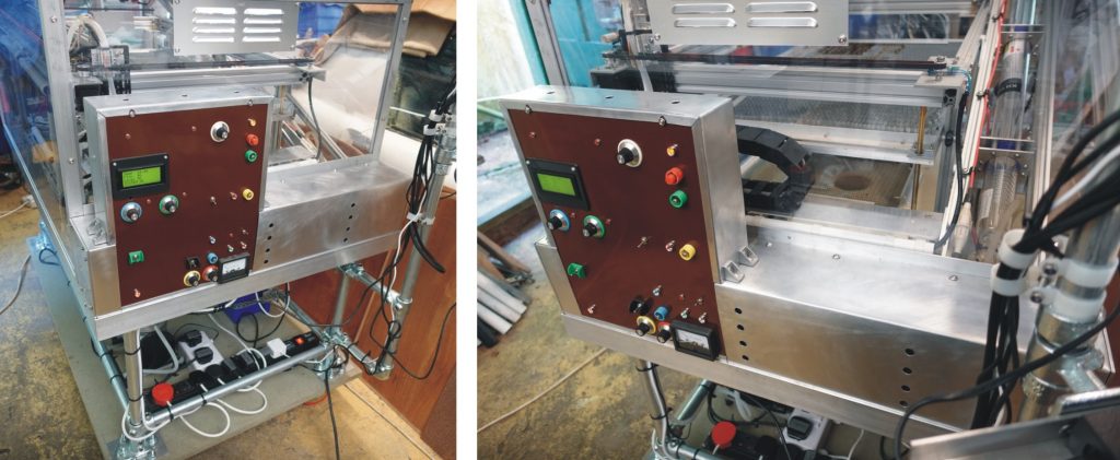
Some details – riv nuts
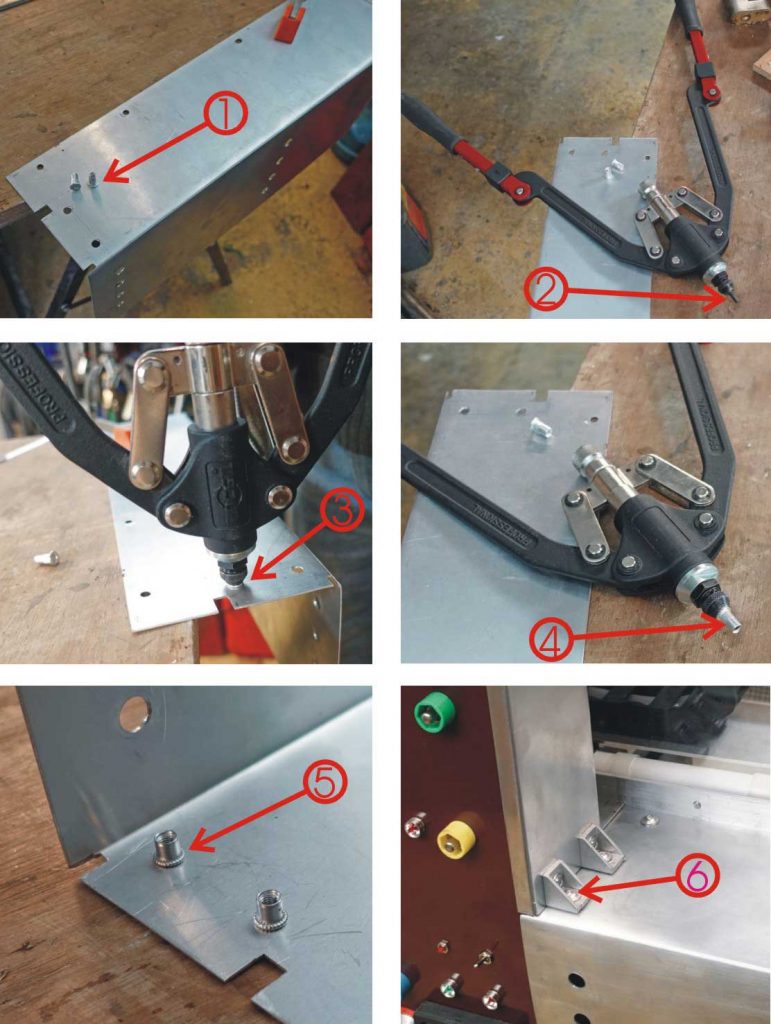
Most of the construction of this project involves M5 screws fixing into 3mm aluminium tapped accordingly (apart, that is, for the 100+ T-nuts needed for the V-slot extrusions). Sometimes I needed to secure two pieces of 1.2mm sheet together and that’s where riv nuts can come in. They are threaded inserts (1. on picture) which, once inserted into a hole, can be collapsed so they spread out and lock or rivet themselves into place (very much like a pop rivet).
An insertion tool is needed (2.) which has a thread on its nose on which the riv nut is screwed (4.) The riv nut is inserted into the hole (3.) and the handles of the tool are squeezed together. This pulls the screw thread in and collapses the riv nut locking it into place (5.) I used some of the angle brackets I had used to assemble the v-slot extrusions to fit the pieces of the casing together (6.)
(Uncollapsed riv nuts are handy to provide a thread in timber. I there is not going to be much “pull”, just Araldite the nut into a hole from the front. If there is going to be a bit of “pull”, Drill out the thread of a nut and insert it into the front as a “finisher” and fit the nut which will do the holding from the back where it’s flange will hold in place.
Completion?
Until or unless I think of any improvements / changes, I reckon the laser cutter is complete. Now I just need to use it. Got a few projects in mind… but first I need to complete the doors for my (very) old project.
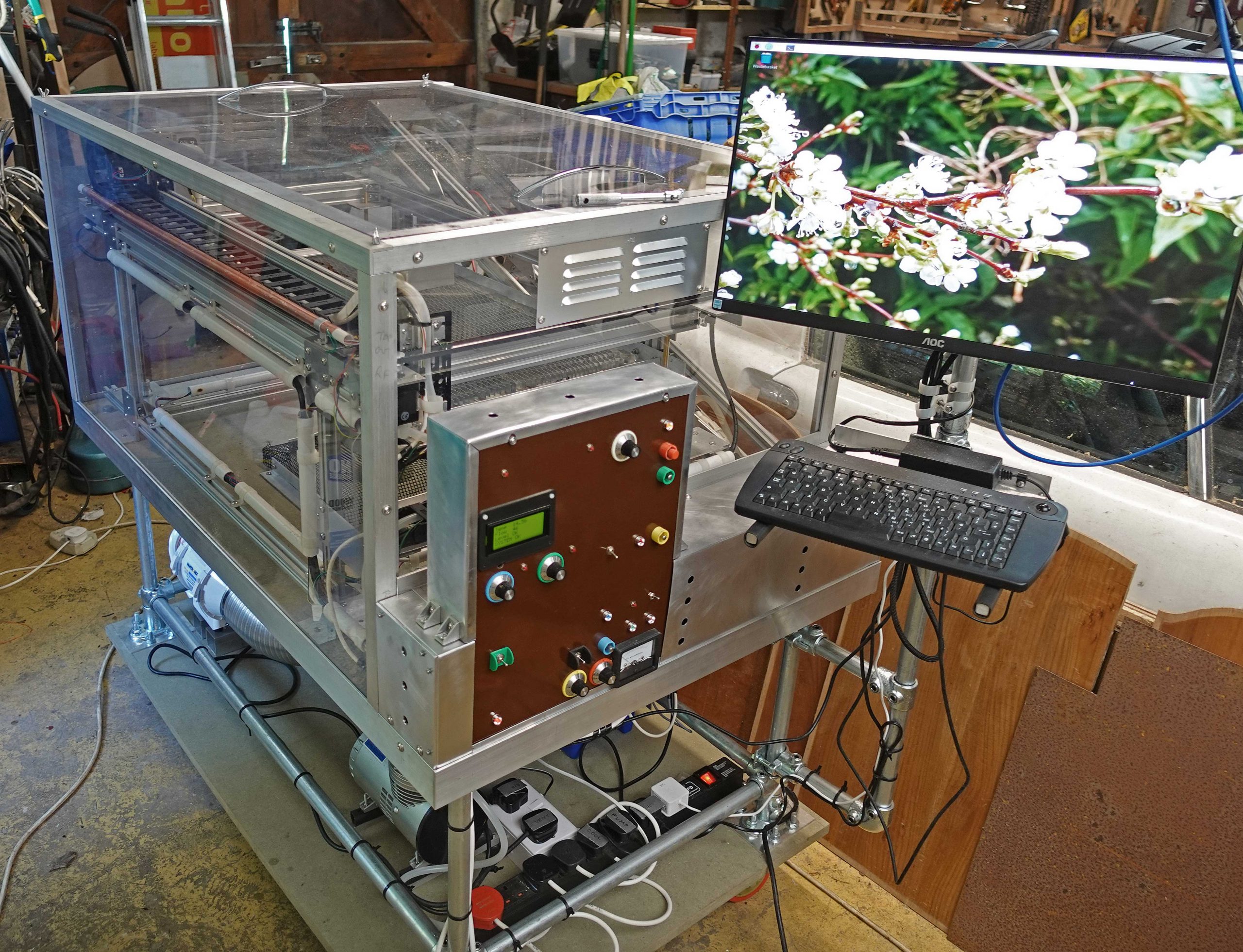
“Improvents” or displacement activity?
Already(!) I’ve found a small “improvement”! I was getting fed up adjusting the laser power with a knob marked 0 – 9 when the adjustment, via the rotary switch is 0 – 11. (By the way, 12 as a base for measuring, rather than 10, is excellent in a number of respects. For example twelve has factors 2,3,4,6 whereas 10 has only 2 and 5. So you can divide something measured on a twelve base in four different ways which is handy for setting things out and is the reason that I often still use feet and inches – it’s not a Brexit thing, I most certainly voted to remain!)
I cut an annular disc suitably engraved with the required numerals. As they were quite small, I felt that the engraving should be a single line rather than an outline of a solid shape as in ordinary computer fonts. So I drew some numbers in Bezier curves on Corel Draw (but it could have been in Inkscape). As always, I had to export them to Inkscape anyway as I need to convert to .svg files for LaserGRBL etc.
As it was, the numerals were quite large and could probably been lasered as outlines after all. I must try this later. Another method would be to export the numerals as a jpeg using standard fonts and engrave using raster mode.
The result was “OK” but I’m not sure why I cut the indexes as slots rather than just dots and with the numerals not quite so close to the edge. Anyway, I Araldited the disc to the knob and filled the engraving with black wax.
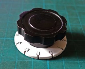
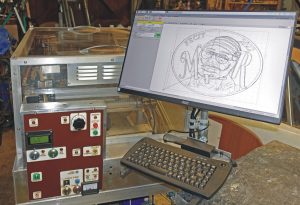
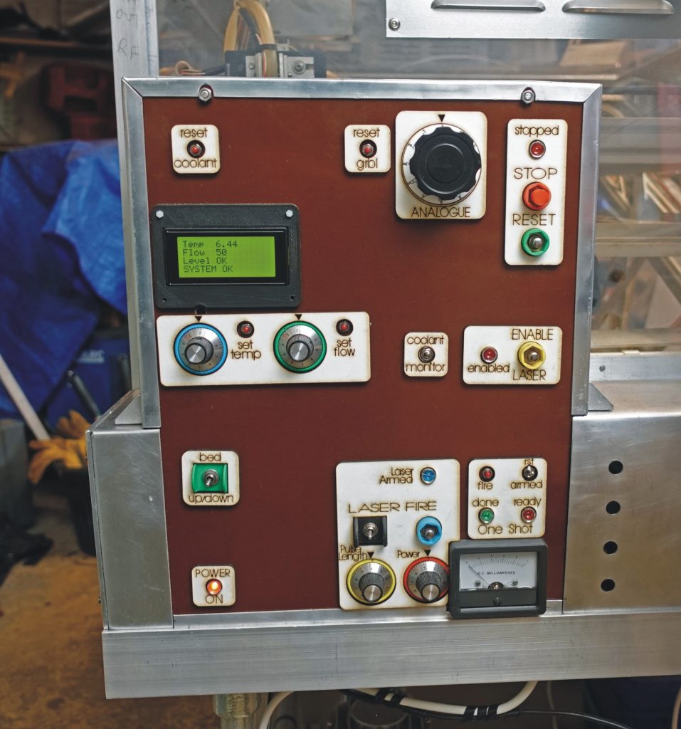
The picture above shows some laser-cut labelling I have applied to the control panel which will help when I forget what the hell these switches and buttons are supposed to do! Now I want to get back to something more creative.
Dragons
Back to something “more creative”. I decided that instead of engraving the dragons and filling the lines with colour, I would cut the background and the dragon in two different colours. This would leave me with what amounted to a fairly complicated jigsaw as I removed tiny pieces of one colour and replaced them with the other colour hut, hey, the nights are drawing in and there’s not much on TV (BBC etc. Sky, Netflix, Amazon Prime – what a waste of time eh?).
The idea is to assemble the panels, right and left, tape the top surfaces to keep the bits together while turning them over, then squeegeeing rapid epoxy into the gaps, covering with some sort of release paper (silicon paper?) and placing under a flat panel with weights or clamps. That’s the theory anyway!
Testing, testing
I did some tests on the white 3mm acrylic I’m going to use for the background. I wanted to know what the lowest setting (tube current) would be required to cut. I set S75 (half power) and tried cutting small circles at various “analogue” settings. Position 5 didn’t quite cut, 7 blasted through leaving position 6 as the Goldilocks value.
Then I tried testing some concentric circles resulting in a range of rings of decreasing thickness to see whether the finer parts of the dragon could be cut. This seemed to go OK except the air blast knocked out a few small bits. I tested without air blast and it seems that it is not so necessary when cutting this quality of acrylic. (However, this does suggest that I need to fit an air bleed valve to reduce the blast pressure.)
Since there are many small bits in the dragon, I tried cutting it on a piece of scrap hardboard. This is another reason to keep the cutting power to the minimum needed as blasting through at a higher current burns the hardboard, staining the back of the plastic. The test was a bit of a failure as even at the lowest power to cut through the acrylic, oily, tar vapour came through and messed up the result.
The picture below, top left, shows the brown muck on the front of the acrylic. Below, bottom left shows the muck on the back of the acrylic (in fact it doesn’t look totally unattractive and I might come back to this in a future project). I tested cutting on an artificial slate but that deposited black bits on the back of the plastic. I tried glass which produced a good result but I didn’t have enough to hand for the job. Then I remembered some unused floor tiles and they worked quite well (below, top right) it seemed. However, I found that some of the cuts were just not quite though which made it a pain to separate some of the bits (using the point of a craft knife to lever them out). I suppose the tile “sucked” some of the heat out) they had been stored outside and were quite cold). Perhaps I could have heated them in an oven first to, say, about 40 -50 deg C.
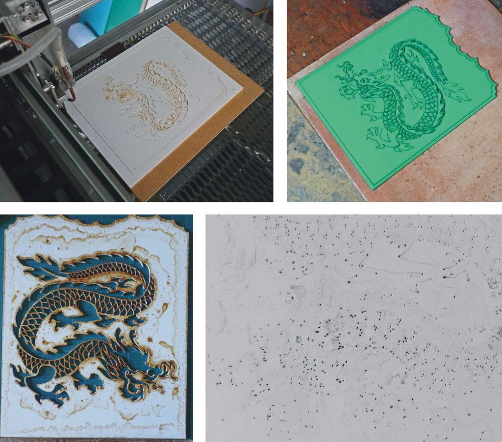
I think there were some reflections from the tiles as when the cut made it through the acrylic, the back of the cut was messy with little holes (picture above, bottom right). This could also be a bit of interaction with vaporised tile glaze. All in all, don’t bother cutting acrylic on ceramic tiles! So what works when very small pieces are being cut? Glass?

However, see above, on the surface of the tile it has left an image which looks quite interesting. I think the black in the marking comes from the cutting of the acrylic. So to achieve this effect it might be necessary to cut through some sort of coating on the tile (isn’t it some sort of special coating which enables low power lasers to mark metals?)
Anyway, I decided on a further variation on my original design. I am now combining the white lasered dragon with all its “bits” removed overlaying the engraving of the dragon on the recycled white-faced particle board.
I used the dragon with the oily deposit having cleaned most of it away with a mixture of all the solvents I had which would not dissolve the acrylic (white spirit, petrol and meths) followed by strong detergent. Most of it was removed leaving some light marks on the back.
Then I cut out a new left hand dragon resting it on the honeycomb without any backing. As I was not going to use the “little bits” it didn’t matter if some would drop out. This resulted in expected clean cut (picture below, top right shows the rear of the cut).
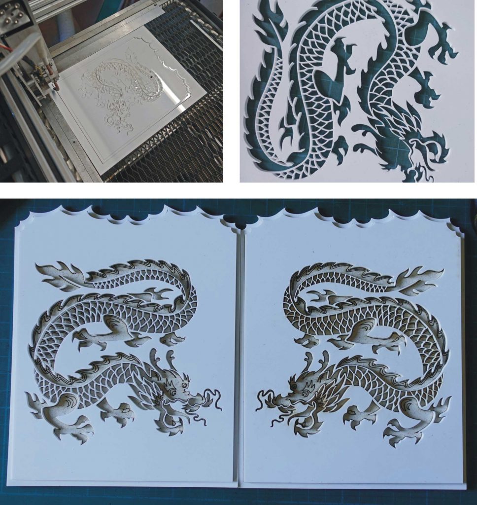
Above, you can see the left and right hand dragons resting on the engraving. Looks quite good, I think. Now I’ve got to glue it all together.
But first another diversion…
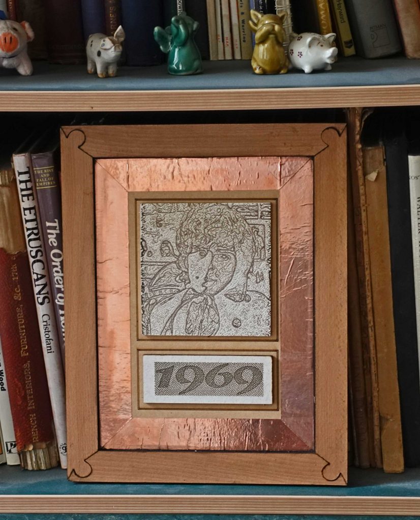
This is a bit of a low quality item (and I don’t just mean the subject!) I want to say that the roughness is intentional like the wrinkles in the copper but… However I did learn more about cutting speeds and power levels.
Anyway, the frame is cut from some more scrap from my old kitchen cabinets. Under the veneer it is rather course chipboard and doesn’t cut very well leaving a poorer fit at the “mitres” than I would like. It was clamped up using a tape clamp and glued together at the corners with PVA wood glue.
The backing is hardboard from packing used in the consignment of aluminium sheet I received recently. The copper is some anti-slug stuff. The picture of me is a slightly different raster-etched pic of yours truly (similar to the ones described previously, the result of some Photoshopping) etched onto some kitchen cabinet rear panel material. The “1969” (the year of the original photo!) was drawn in CorelDraw and exported as a jpeg and rasterised by LaserGRBL. The rest of the gluing was courtesy of Evostik contact adhesive.
Assembling the dragon doors
Back to the dragons. I needed to assemble the white faced particle board engraving, the white acrylic dragon outline and the two edging pieces (green over white) and then glue that assembly onto the door face (I had made that white panel fifty years ago, rather unglamorously, out of two pieces of white Formica glued back to back.)
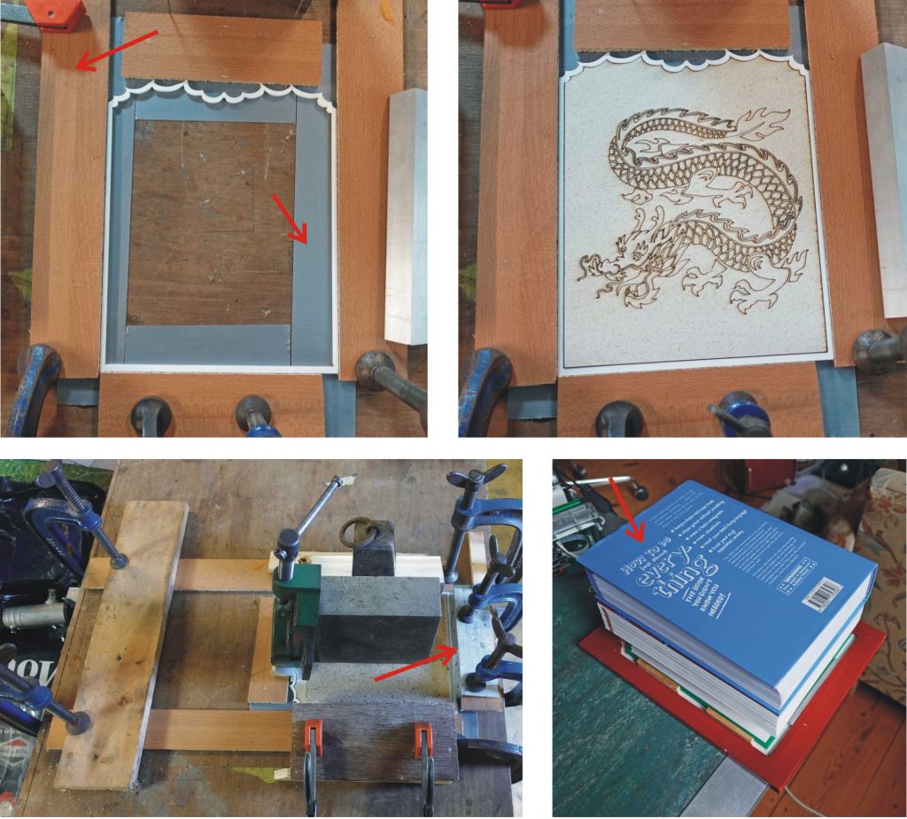
Picture above, top left – arrow: So that leakage of adhesive wouldn’t glue everything to the bench, I first laid down some Gorilla Tape to which the glue will not stick (I hope!) To get everything to line up, I clamped some strips of thin (effectively) chipboard to the work surface to fit closely round the dragon assembly. The chipboard is quite weak in cross section and can be separated from the assembly quite easily if any glue escapes. Tiny bits of chipboard remaining stack can be removed with a knife. (A better way might have been to put Sellotape on the strips.)
I used Clear Gorilla Glue to bond everything together. This adhesive has a certain amount of gap filling ability and can be applied from the nozzle of the bottle where you want it much more easily than applying Araldite with a spatula. I applied it to the edges of the white faced engraved board and the edge of the perspex outer and put both bits into position (top, right). I weighed down the engraving with a heavy piece of steel on top of a piece of board. I pressed down the thin acrylic outer with the edge of a piece of aluminium angle weighed or clamped down as can be seen in the picture (bottom left – arrow).
After a few hours, I remove the weights and clamps and applied adhesive to the engraving in positions where it would not spread out and be seen through the piercings in the laser-cut top layer. I replaced the weights and clamps a left it for 24 hours to set.
After removing the assembled panels, I cleaned off surplus adhesive from the edges and prepared to glue them to the doors which I had remove from the cabinet. For this I used about six blobs of Andradite. I used wooden spacers to get the panel in the correct position a weighed it down with some books (bottom, right).
Finished (after 50 years!)
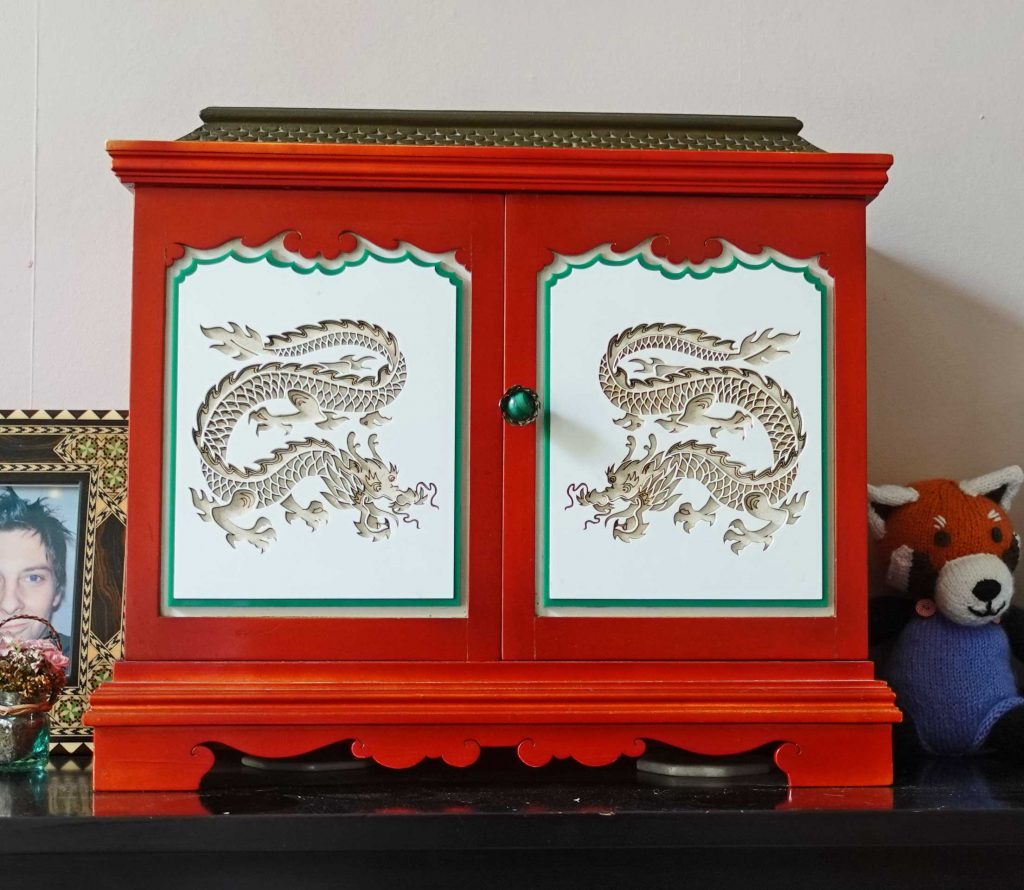
Box project
I thought I’d try making something a little three dimensional. The original idea was to make the box “flat pack” held together with knitting needles, perhaps (see sketch). I had bought some 3mm hardwood ply from Wickes to try out, so I used that and changed the design a bit to be glued.
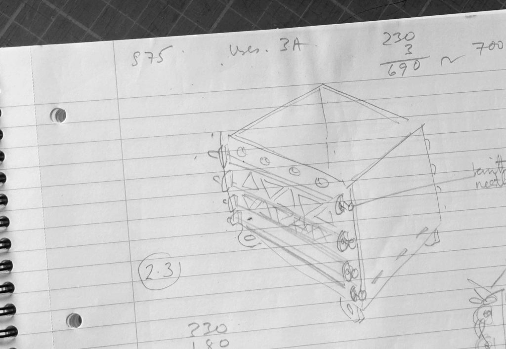
I drew out the parts on CorelDraw, followed the usual palava exporting to Inkscape and stretching to the correct size. The easiest way to do that is to include a rectangle around your CorelDraw drawing, of known size, setting guides in Inkscape to those dimensions, importing the .cdr file, then stretching so the rectangle hits the guides, then deleting the rectangle. Then it’s save (.svg file) then load in LASERgbrl, output GCODE then sent to the laser cutter Pi (By VNC). Of course, you could do the whole drawing in Inkscape if you were familiar with that (which I’m not, yet!)
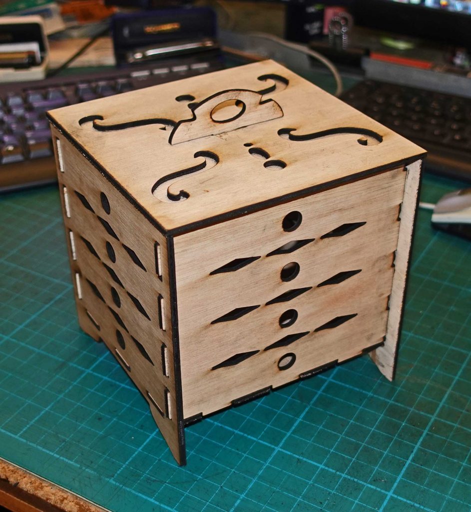
The hardwood ply needed almost full power (S140) at F200 to cut and was lacking in crispness with a bit of charring. It looks OK at a distance. The pattern suggests drawers, so that might be a future project (I’m thinking Christmas presents here!)
Anyway my ideas have turned back to my “flat pack” idea now made out of black acrylic so I’ll see how that goes.
Black Hole Box
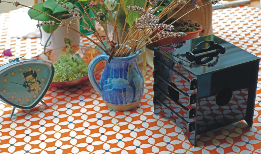
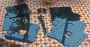
Moiré effect laser “print”
I decided to try printing (engraving) onto paper. I had a few sheets of heavy “art” paper but rather than potentially wasting this, I decided to start with some cheap 80gsm(?) paper.
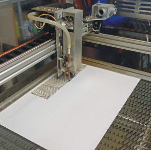
I took some pictures of leaves and bits and bobs round the garden. I chose a picture of some fern fronds, increased the contrast a bit, resized in CorelDraw to just under A4, exported it as a JPEG and opened it in LASERgrbl and produced a raster-type GCODE file which I loaded into the laser cutter.
At S75, F1000 and “analogue” switch position 3, this gave a current of a few mA. I found that the laser completely cut through the paper and after about four hours, left a gossamer web which was almost transparent. I tried the effect of putting this over various colours but the most interesting result was over kitchen foil. When this viewed at different angles or slightly moved about, the fine gaps in the print/cut reflect back from the foil and being slightly displaced from the laser cut itself, interact to give a moiré effect.
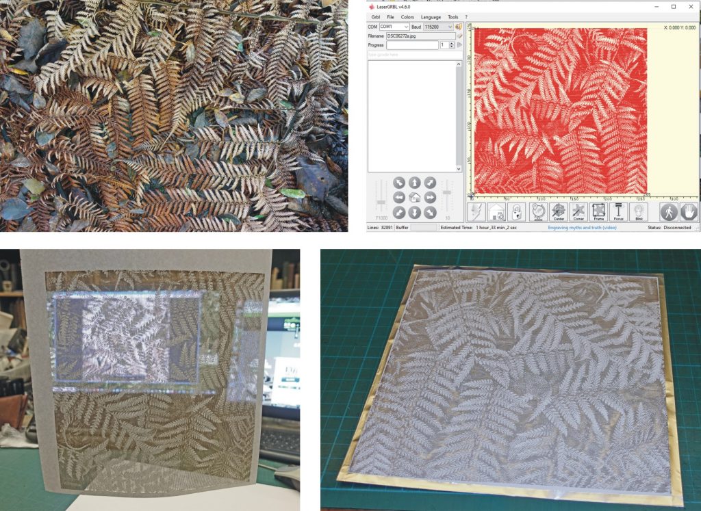
Above, clockwise from top left: 1) picture of fronds, 2) picture loaded on LASERgrbl, 3)cut/print can be seen through, 4) cut/print with foil backing.
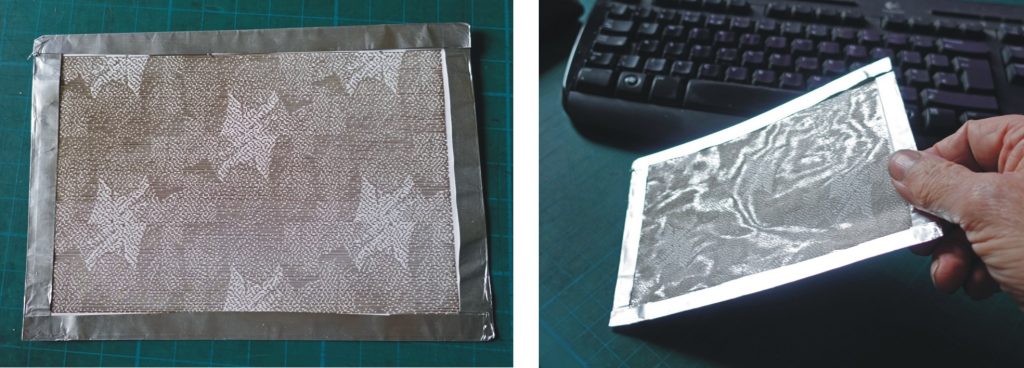
Above, left: A smaller cut/print of some magnolia leaves. Right: This shows off the moiré effect.
Design for a Christmas card
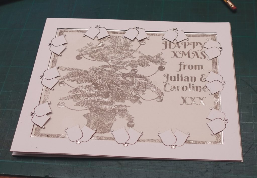
Above, the card shows a tree with a greeting, again, raster-engraved/cut and backed with kitchen foil. The effect comes about when the card or the viewer moves, revealing a moiré effect. Below, the “bells” are cut out separately and overlaid.
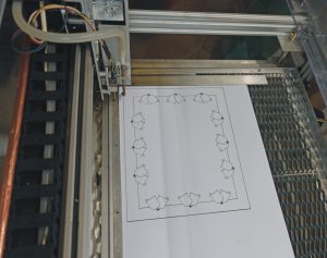
Miscellaneous stuff
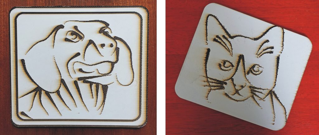
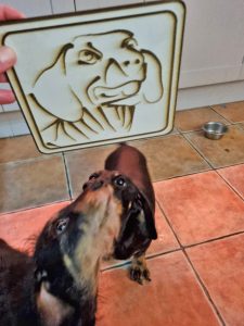
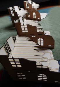
Glass engraving
I’ve tried some glass engraving at low power on 2mm picture glass. The results have been successful but I feel I am at an experimental stage as yet. I notice the engraved lines show up as a series of tiny blobs. I assume this is a function of the laser pulsing under grbl control (?) It’s not unattractive but I would like to produce clean lines. Perhaps I should slow down travel with lower power?
I’ve used the dragon pattern again and illuminated the edge with Adafruit NeoPixel LED strips. These are driven by an Arduino Uno running library software from Adafruit to sweep continuously varying colours across the engraving. For Christmas, I substituted an engraving of Santa!
(I initially tried driving the NeoPixels with a Raspberry Pi Pico – £3.60 compared to £19 or so for the Uno – however, programming using the Arduino IDE, the software didn’t work properly with flashing rather than smooth transitions. One for future investigation!)
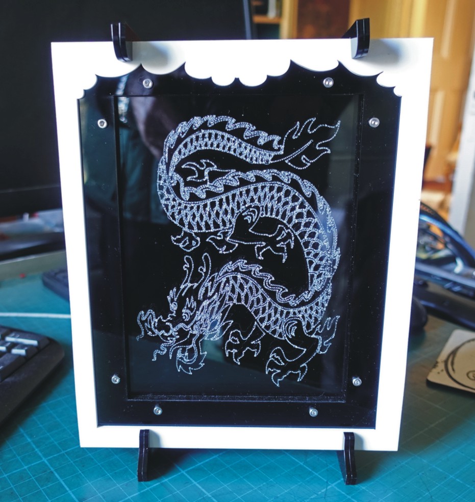
Above: The engraving in a frame laser cut from acrylic (unilluminated). Below, left: The frame with the rear panel removed showing the strips of NeoPixels. Below, right: The Arduino mounted on the back.
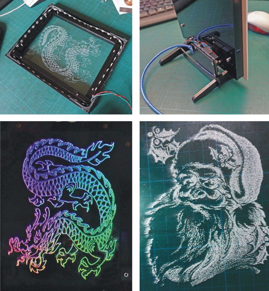
Above, left: The dragon illuminated. Above, right: The engraving of Santa (unilluminated).
How did I exist without it all those years?