
(See here for Boiler Circuit, valves etc. and here for Software and here for Arduino Watchdog)
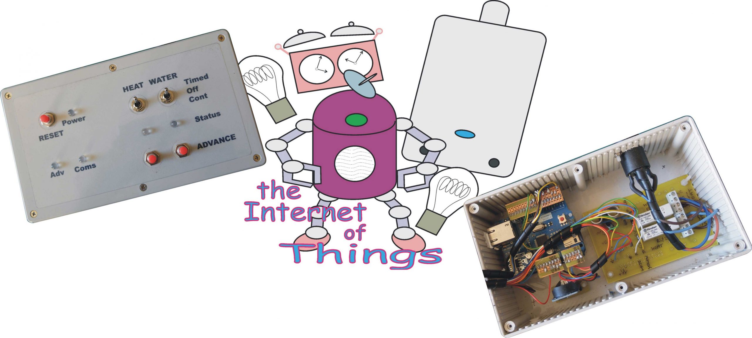
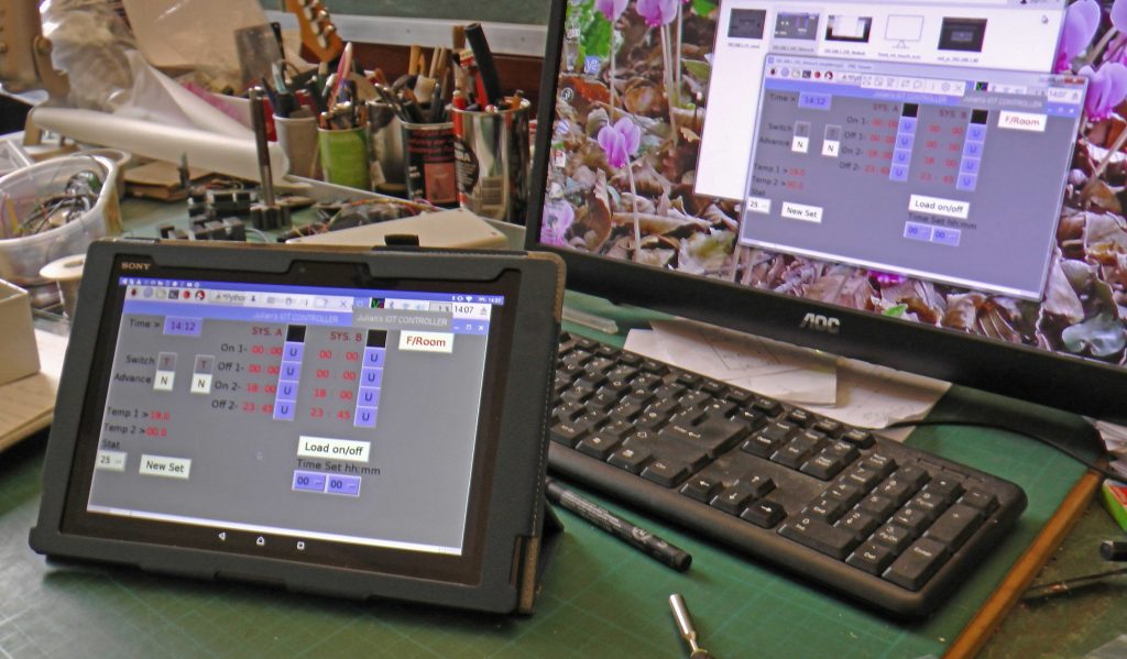
This is a back to basics (sort of) Arduino-powered timer which has some basic controls on the unit but avoids digital displays and tedious pressing of two or three buttons repeatedly within layers of menus to get the on/off times, clock settings etc. into the system. IMHO these settings are much more easily input from a PC, tablet, mobile phone etc. over the local network (or perhaps, the Internet). A control program written in Python running on a Raspberry Pi talks to the Arduino over the network using UDP. This can set on/off times, adjust the thermostat etc, The control screen can by brought up on any device connected to the network running the virtual desktop program VNC. In the picture below the control screen is running on a PC and an Addroid tablet.
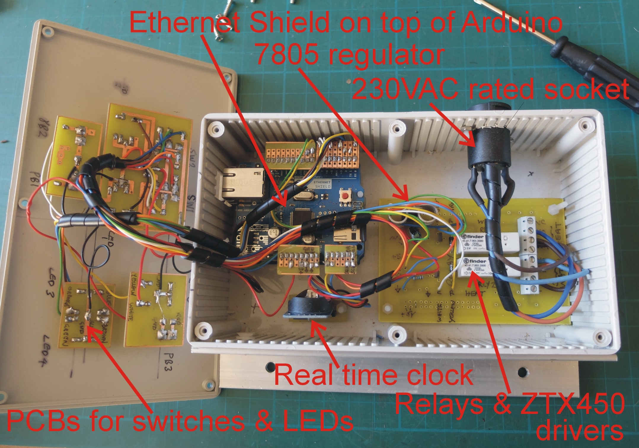
In this version of the project, the electronics comprise an Arduino Uno with a Ethernet shield (which also has provision for an SD card to save the on/off times, thermostat settings etc.) and a DS3231 real time clock module with battery backup. The Uno can turn two relays on or off which in turn, control the room and water heating. (How this relates to the boiler, pump and water control valves is described later.) There are sockets for two I2C temperature sensors. There are two toggle switches which can override the timer, two buttons to advance the timer and a reset button. Five LEDs provide information about the current state of the system. In case of software glitches, hang-ups etc. there is a watchdog circuit which will reset the system. The unit will have been in operation for five years continuously come July 2020 and it averages only about one glitch a year. In all cases the problem has been with the DS3231 clock suddenly registering the wrong time. (It’s probably a good idea to replace its battery on a yearly basis with one of a reputable make.)
Boiler Timer Circuit
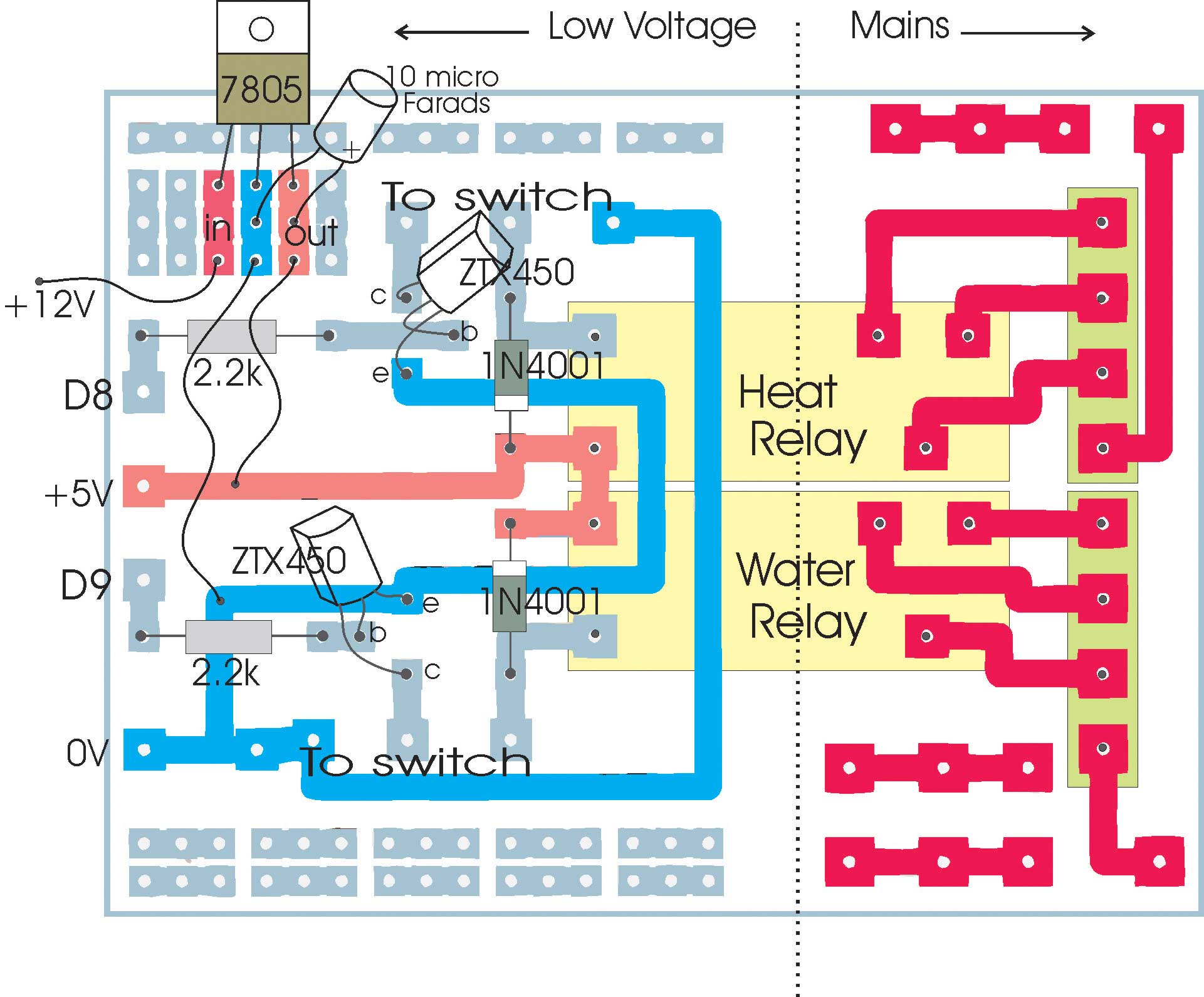
The circuit is reasonably simple. The main elements are an Arduino, an Ethernet Shield, a real time clock module (DS3231 from Ebay – very cheap but supply a new branded backup battery), mains- rated relays (5 volt coils SDDT contacts from Rapid Electronics). The temperature sensors are SparkFun TMP102 with a bi directional logic level shifter also by SparkFun (Cool Components or Pimoroni). The level shifter is needed as the TMP102 runs at 3.3V and the Uno at 5V. The “D ” and “A” numbers refer to the digital and analogue pins on the Arduino.
There are two three-position toggle switches providing manual control of the relays. In position 1 the relay coils are connected to the ZTX450’s collectors (i.e. controlled by the electronics). In position 2 they are connected to nothing (i.e. off). In position 3 they are connected to ground (i.e. continuously on). This provides absolute control of the system independent of the electronics or software (as long as the 5 volt supply is maintained!)
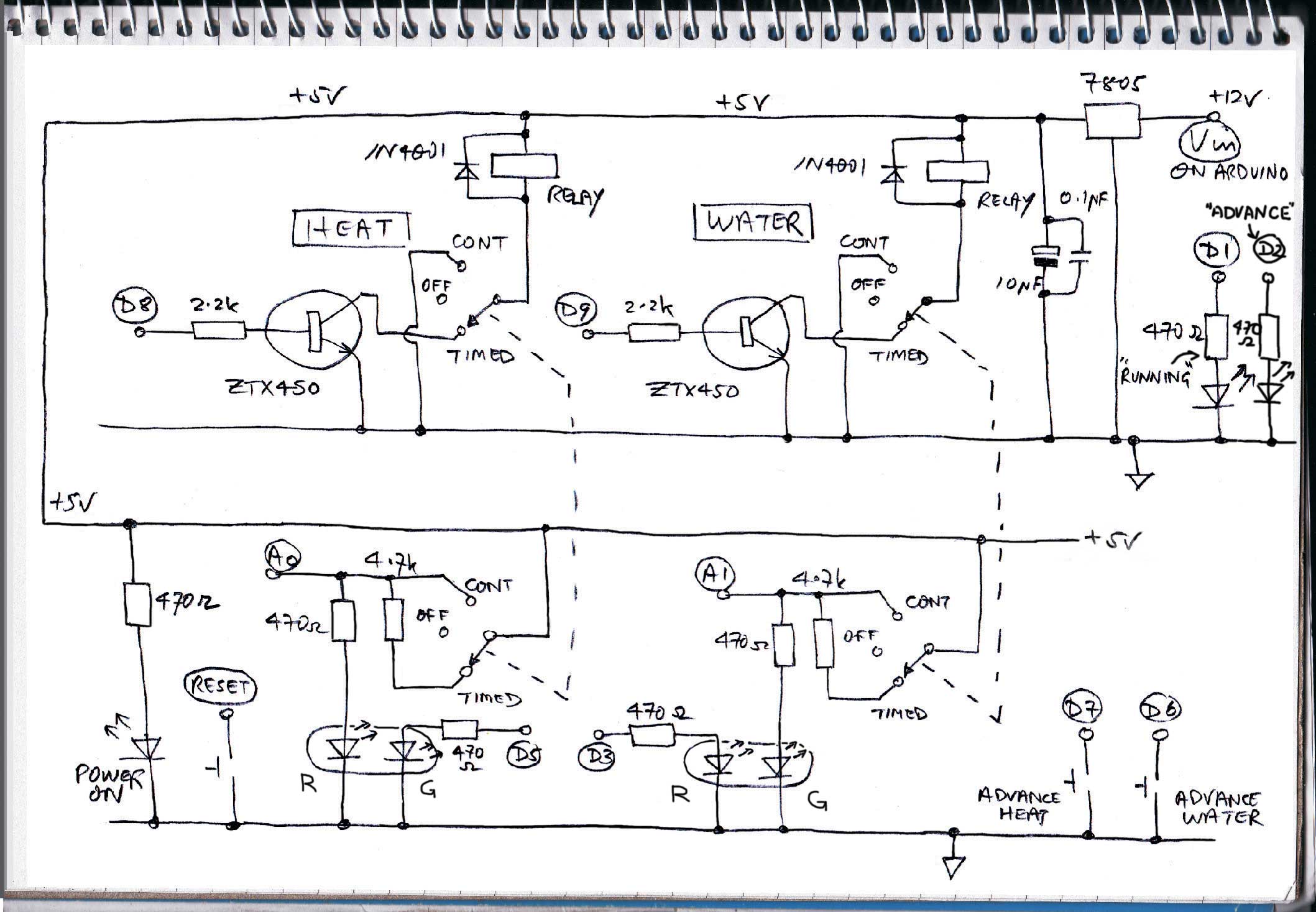
The switches are 2 pole. The second pole is used to let the Arduino know what the switch positions are (largely so they can be reported back to an application running on a remote computer. I used analog input ports to do this to economise on ports used. The resistors and the LED form a potential divider whose output to the port varies with the position of the switch.
The LEDs are tri-colour and are connected up to produce various displays according to the status of the timer. When a switch is in the timed position, the status LED shows red when timed to be on and faint green when timed to be off. When a switch is in the off position, the status LED shows flashing red when timed to be on and is off when timed to be off. When the switch is in the continuous position, the LED shows green at all times.
There are three buttons. One is reset (connected to the Arduino reset) and two advance the heating and water programs to the next timer event. (Advance is cancelled by pressing reset.)
Apart from the two tri-colour LEDs metioned above, there are three other LEDs. One indicates power is present, one indicates the advance function is in operation and one is linked to D1 on the Arduino. This pin is used in Arduino serial comms and if it is flashing, it indicates the Arduino is operating and not “hung” (just in case!) This is linked to the watchdog circuit – see later for details.
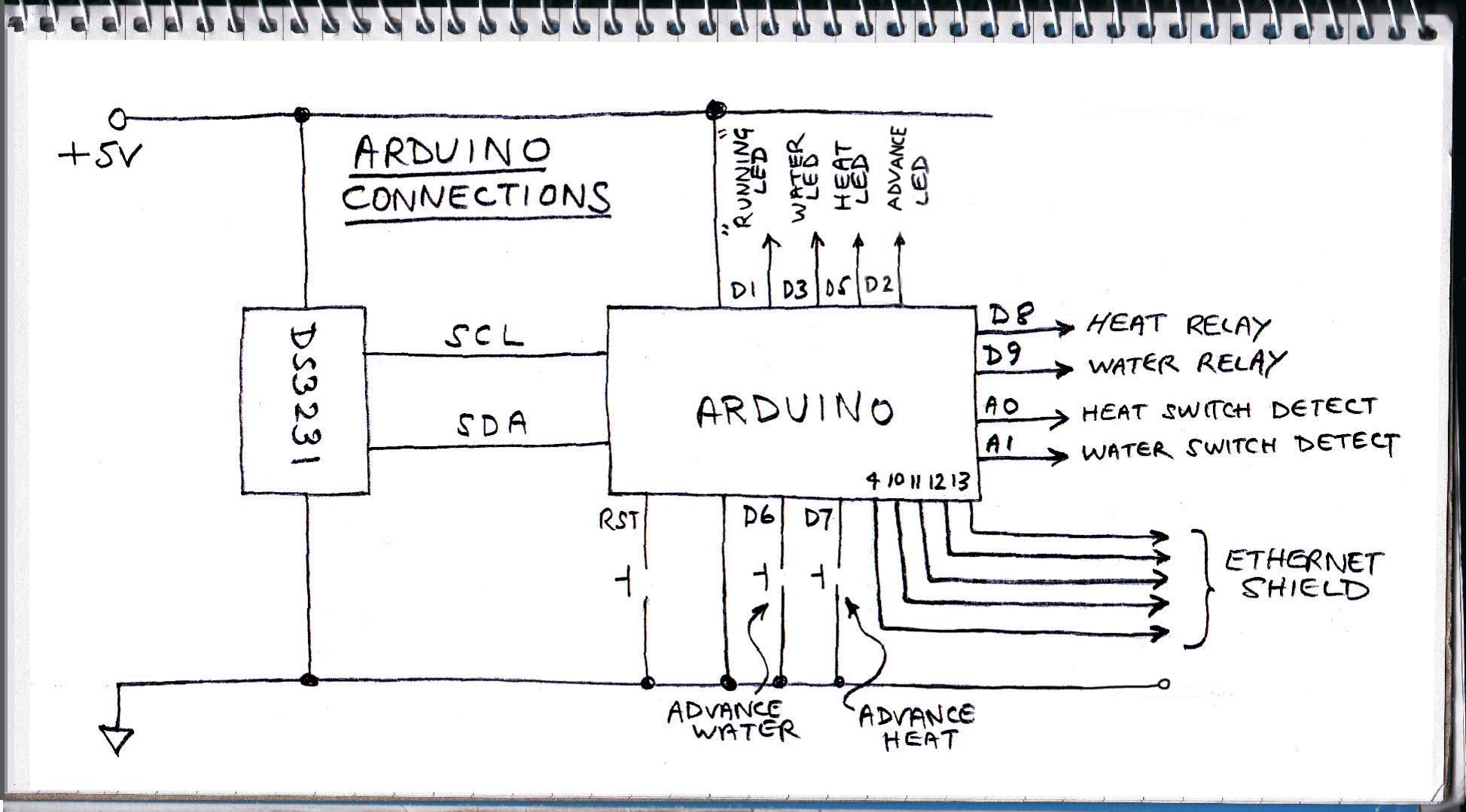
The diagram below shows the connections to the Arduino.
Component list
Parts list (less watchdog – see later for this.)
1 x Arduino Uno
1 x Arduino Ethernet Shield
1 x 8 Gb micro SD card
1 or 2 x TMP102 breakout module, Sparkfun
1 or 2 x Bi-directional logic shifter, Sparkfun
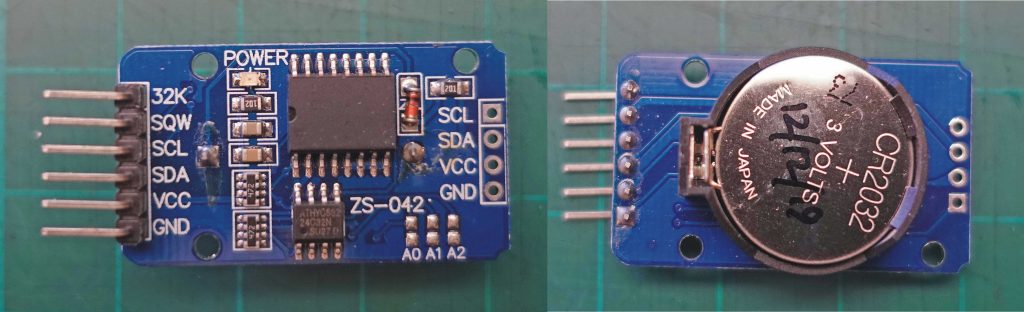
1 x Real time clock DS3231 (search for this on Ebay)
1 x 2032 battery (don’t trust the one the DS3231 came with!)
Some 0.1 pitch header strip (Ebay)
1 x Hammond plastic box 191x110x61, Rapid Electronics 30-6250
1 of each Clifcon touch-proof plug and socket, Rapid Electronics 20-0807, 20-0810
2 x Taiway DPDT centre off toggle switches, Rapid Electronics 75-0214
2 x 4 way Camden Boss terminal block 5mm pitch, Rapid Electronics 21-4731
2 x Finder PCB mount relay 5VDC 10A SPDT, Rapid electronics 51-0535
5 x 5mm tricolour LEDs, Rapid Electronics, 55-0170
3 x Push to make switches, Rapid electronics, 78-0030
8 x 470 0hm resistors
2 x 4.7 k Ohm resistors
2 x 2.2 k Ohm resistors
1 micro Farad electrolytic capacitor
2 x 0.1 micro Farad capacitors
2 x 1N4001 diodes
2 x ZTX450 or similar transistors
1 x 7805 1A regulator
Strip board (Vero board or similar)
RJ45 sockets (I used these for the temperature sensors but other types would suit)
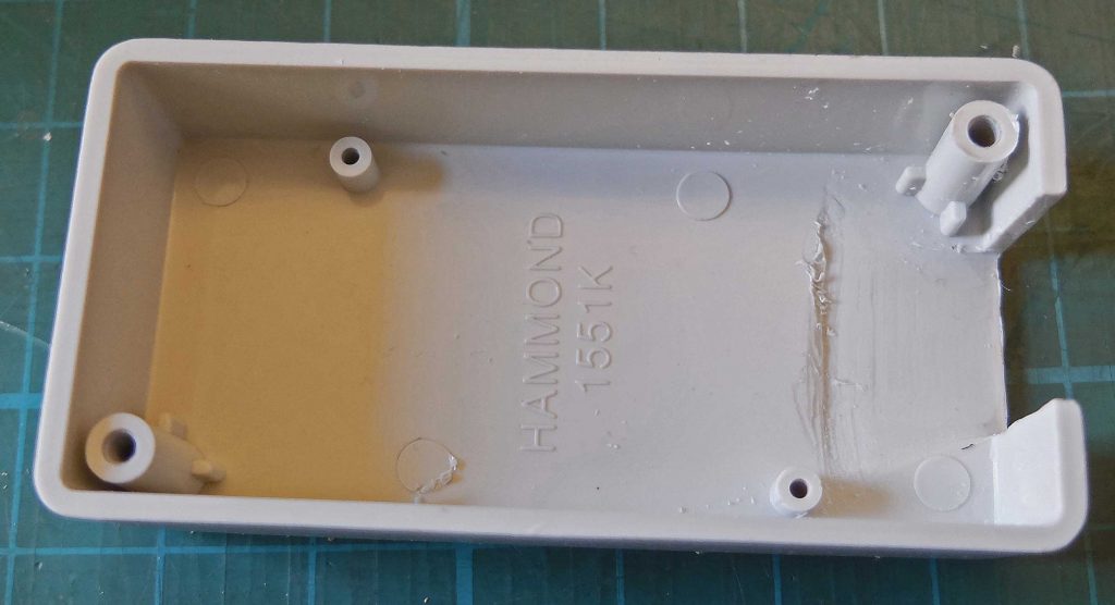
1 or 2 x BS box, grey, 80 x 40 x 17 Hammond 1551K
PCBs – these have to be made!
Connecting wire, nuts and bolts, solder etc.
12 volt power supply (Ebay, Amazon etc.)
Ethernet cable (Ebay)
HomePlug system or similar, if needed – sends Ethernt though the mains.
Arduino and Python and possibly Processing software (open source).
The relays are driven by a couple of ZTX450 transistors or similar 1 amp general purpose transistors.
Construction
Below is a diagram of the main PCB and component layout (top view). I design my PCBs using free DesignSpark software. I generally don’t use auto-route and just bang the design together by eye to look as much like my hand-drawn circuit diagram as possible. One day I’ll move on up to the 21st century! If anyone wants a copy of the design, just ask! By the way, I always include extra tracks and pads where there is space to take care of things I haven’t thought of at the design stage!
I print out the designs on inkjet transparency film. I generally stick two designs together to ensure the best opacity. 2½ minutes in my UV box does the trick.
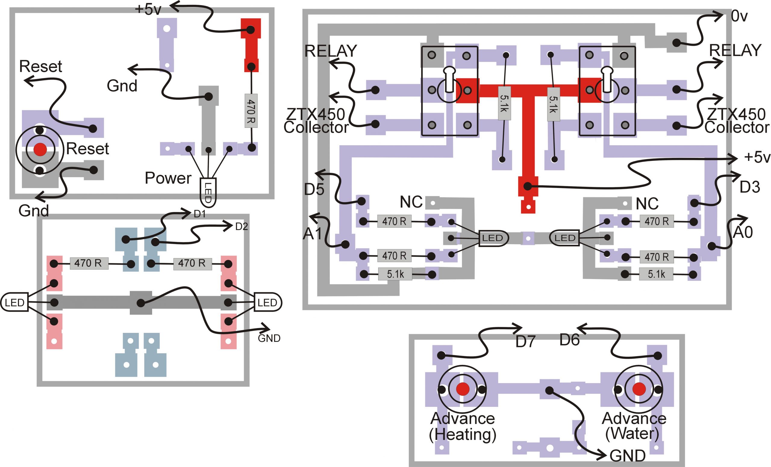
I have mounted the toggle switches, push buttons and LEDs on four separate PCBs so that I could be flexible in positioning them on the box lid (design it as you go along, my favourite method!) Also, the heights of the push buttons and toggle switches are different, thus they do need to be on separate PCBs. So the power LED and reset button are on one PCB, the “advance” and the “coms” LEDs on another, the toggle switches and LEDs on another and the “advance” buttons on the last. These PCBs also incorporate the various resistors associated with these components.
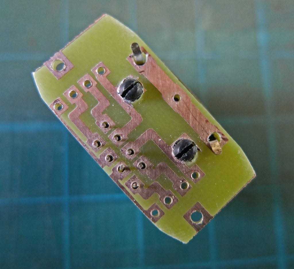
The DS3231 clock module (below) is fitted with right angle headers and plugs into a tiny PCB fitted with female headers. (It could be done on Veroboard – strip board or you could put it on the main PCB.) This enables easy removal and replacement when changing the battery.
The diagram below shows the four small PCBs used for the switches and LEDs. The switches are not intended for direct attachment to PCBs but with a large pad and a bigger hole for the solder tag , there is no problem. The PCBs (and the LEDs) are held in position on the front panel by the switches. On the PCB with just two LEDs, a tight fit on the panel and a tiny dab of superglue does the trick. In the end, I didn’t need the power, “coms” and “advance triggered” LEDs to be tricolour which explains the lack of resistors and connections to the green side of the LEDs (the left hand two PCBs below).
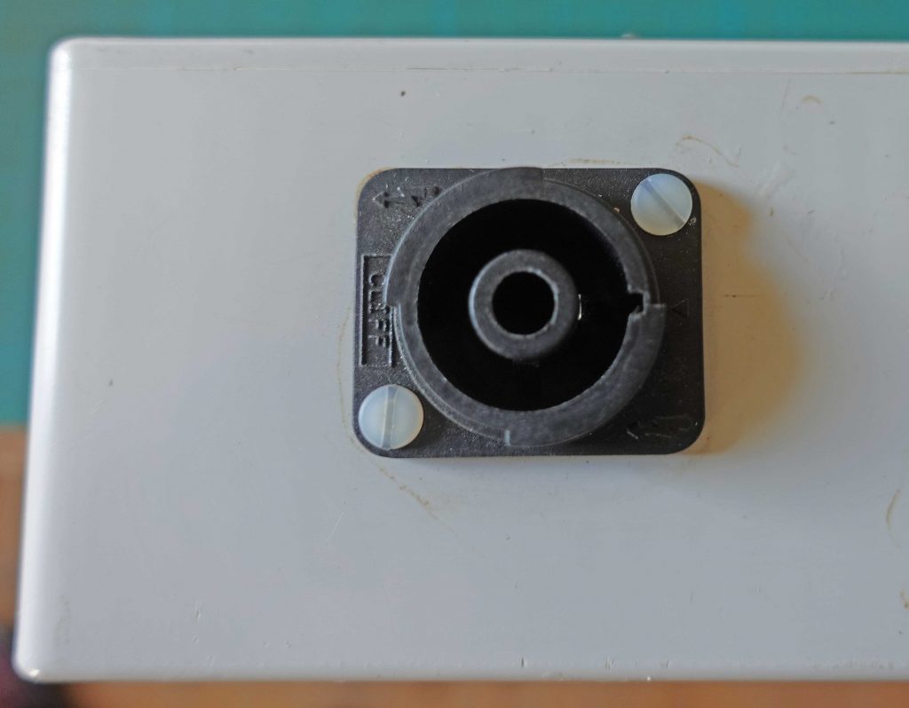
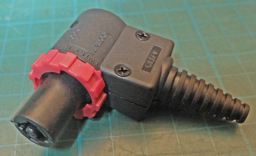
The relays, of corse, are switching mains voltages. The 230 volt rated plug and socket is shielded so that there are no exposed parts of either. These Clifcon plugs and sockets are also very compact and I have used them on quite a nimber of projects. I like to keep the 230VAC physically separated as far as possible from the low voltage parts and try and make it impossible to accidentally touch any live parts with lid off. A 230 volt shock is no joke and across the chest is often fatal! I use nylon screws where possible to avoid any shorts or physical damage to PCBs
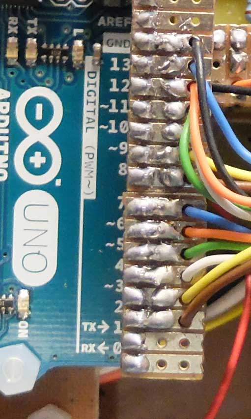
Left: to connect to the Arduino, I manufacture plugs using pieces of copper strip board (Veroboard) with headers soldered on. I pass multi-strand wires down through one hole then back up an adjacent hole for soldering. This provides strain relief for the wire. (Note that this picture is from another project.)
The system shown above is not quite complete because in the picture of the innards of the system, shown a little way above, I have not yet fitted sockets for the temperature sensors. The sockets and cables I have used are RJ45 network types as they are really cheap. You can get flat ethernet cables in many lengths up to 10m or more. These can be fed under carpets and leave no bump. In other projects I have used 5-pin DIN plugs and sockets with multicore screened cable intended for alarm installations which is also a possibility. The sensors communicate by I2C and need SDA, SCL, 5 volts, 3.3 volts and ground so a five-way cable at least is needed. I my house I need round about 10m of cable. I2C is intended for short cable runs only (within a piece of equipment, for example) but I have found that it works of quite long distances. I haven’t noticed in practice whether running the signal wires as twisted pairs or in a screened cable or at 5V or 3.3V makes any particular difference.
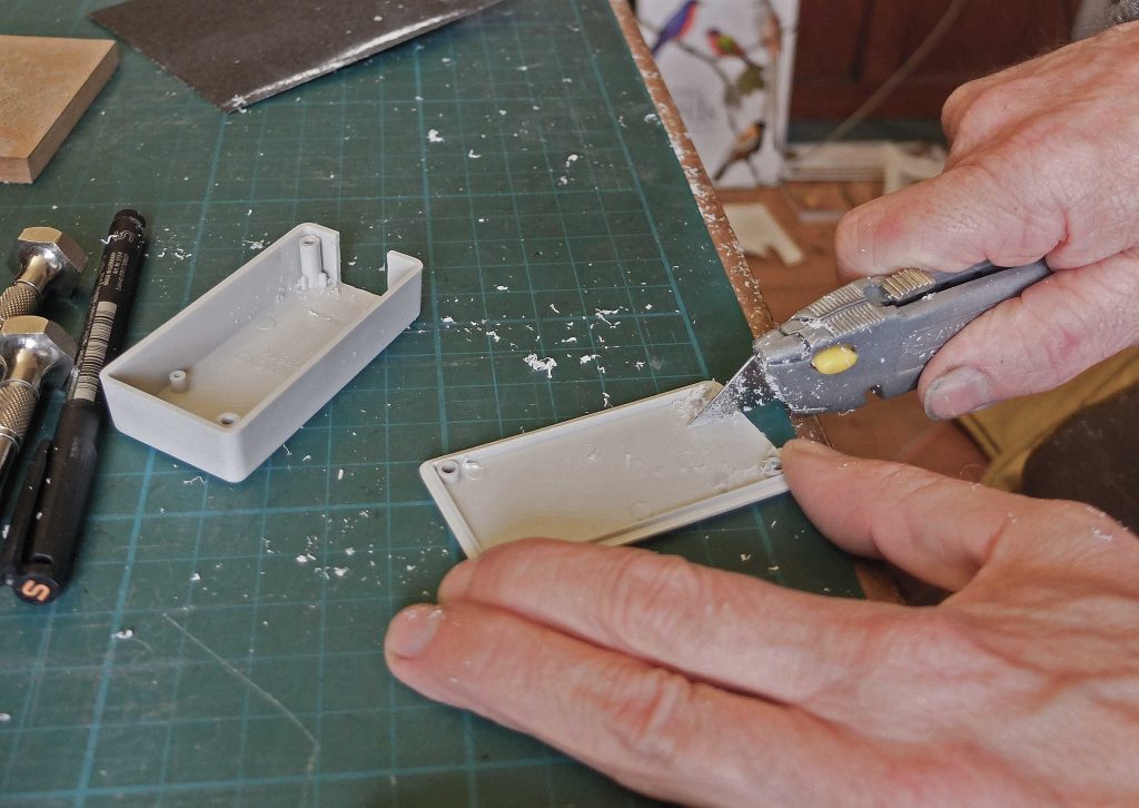
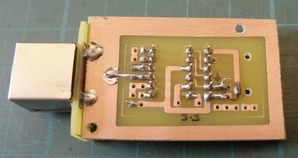
You can get these RJ45 sockets with the PCB pins coming out the back or out of the bottom. In this case, I have used the “pins coming out the back” type and have made up a PCB to accommodate two sockets. I cut a hole in the left hand side of the case for the sockets and screwed the PCB in place. Incidentally, to make a squre hole, drill a round hole and enlarge it with a file or for a cleaner cut pare it to shape with Stanley knife.
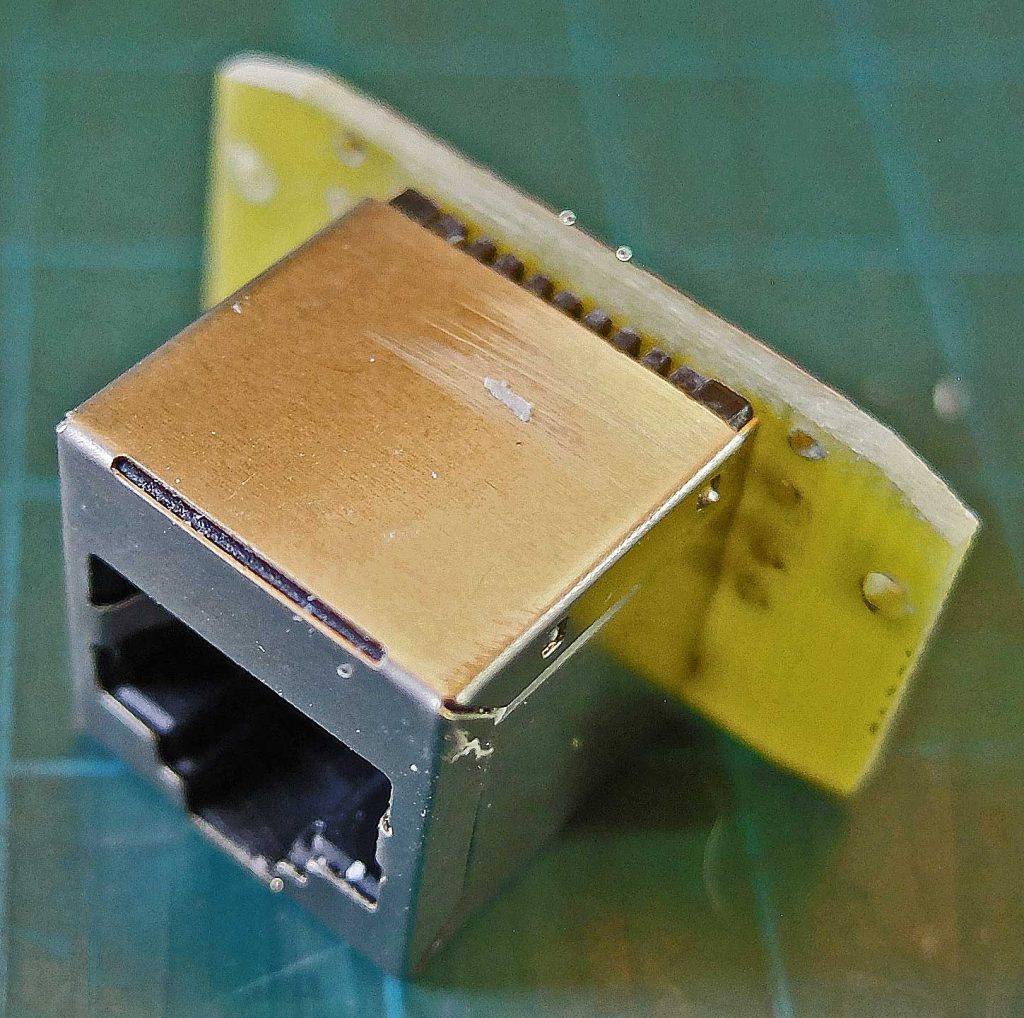
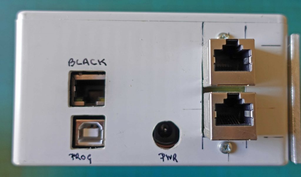
Above left shows an RJ45 socket positioned in a PCB ready for soldering similar to that used on the timer (there, it was a PCB for two sockets). Below, this picture of the end of the timer case shows the RJ45 sockets for I2C connection (temperature sensors) on the right, and the programming USB socket, the ethernet socket and the power socket belonging to the Arduino and Ethernet Shield to the left of them. (The PCB shown above is actually the one used on the temperature sensor described shortly below.)
Temperature Sensor (thermostat)
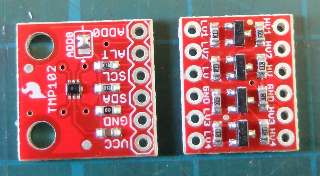
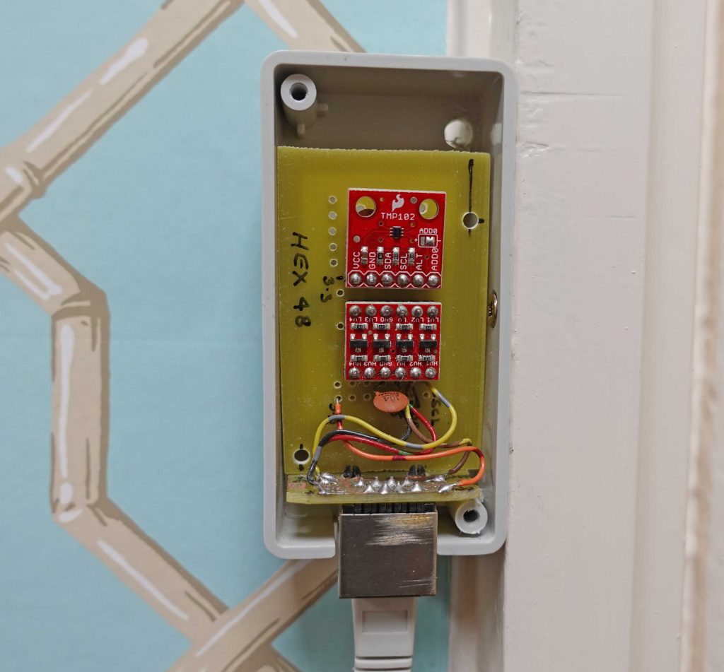
The sensor uses the TMP102 sensor in a breakout board by Sparkfun (purchased from Pimoroni) and, since the sensor works at 3.3 volts and my Arduino at 5 volts, a logic level converter also from Sparkfun. The TMP102 board shown in the picture above is a previous version. The latest board from Sparkfun does away with the solder link (middle top on the board) method of choosing the base I2C address. In the latest version, if you choose an address other than the default 0x48 (hex 48) you have to cut a track and connect ADD0 to the appropriate point.
The case is a Hammond 1551K. As can be seen from the pictures below it needs the hole for the RJ45 and also a little thinning of the case to make it fit. Fortunately, ABS is very easy to carve, scrape etc.
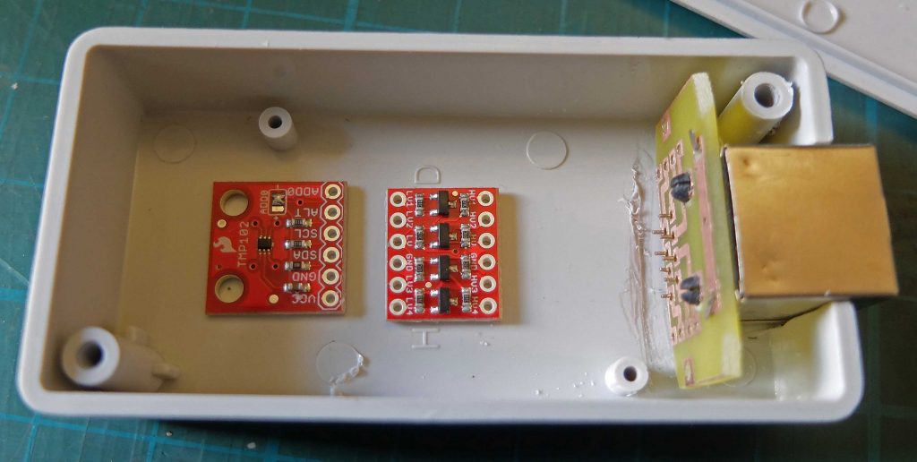
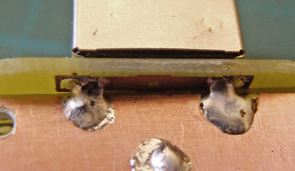
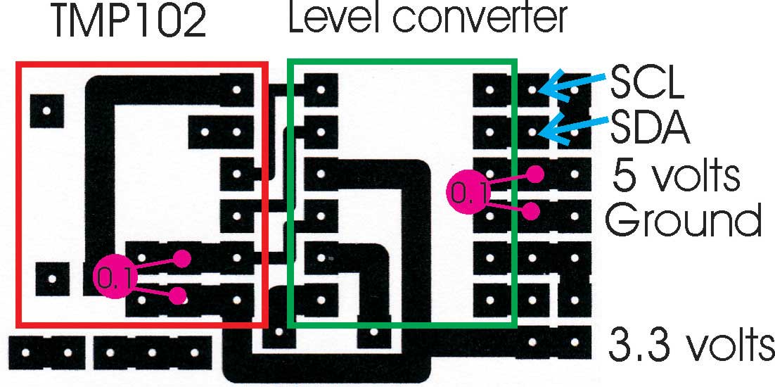
The PCB for the RJ45 and the PCB for the TMP102 and the level converter are fixed at right angles to each other with two large blobs of solder.
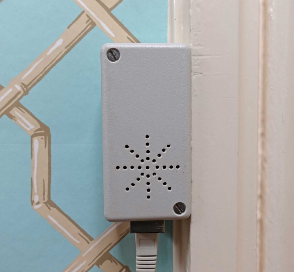
The case is fixed to a door architrave by a small screw through the side. I used a piece of Veroboard as a pattern when drilling the holes in the front of the case using a pcb drill. Using a larger drill, held in the hand, I gently chamfer the holes on both sides.
Next: the circuitry round the boiler, valves and pump.