
Greenhouse monitoring and control using a Raspberry Pi and an Adafruit Feather
Introduction
I originally wrote this on my old site (mr-m.co.uk) in a sort of blog style which resulted in a record of a continuing design process showing how the project developed over a few months. I have largely retained this style as 1) it’s hard work to re-write everything and 2) it reminds me of why I designed the “final version” the way I did. I have tried to add notes as to how the “final design” differed from the original as I go along.
Background
I wanted to use an Adafruit Feather (an Arduino Uno on steroids) to control various things in my new greenhouse. I could have used many other controllers including a Raspberry Pi. I have chosen the Feather because of its ability to run for a very long time (years, perhaps) without crashing (although I have had some problems provoked by a WiFi router crash – more about this later). If the power is cut, it automatically resets when the power is restored (also the Feather incorporates a battery backup facility, although… see later).
Up to now, I have programmed my Arduinos etc using the IDE running on a Windows PC but recently I tried loading the IDE on a Pi3 and using that. (I tried a Pi Zero first, but it was slow.) It worked very well and didn’t have the annoying habit of losing track of the port being used to program that PCs seem to show (at least on my Windows 7 PC).
I took the Pi and the Feather down to the Greenhouse as an experiment and programmed the Feather from the comfort of the house using VNC (I still can’t get over how wonderfully VNC works!) It the occurred to me that I could put a Pi and A Feather in the same box and get the best of both worlds. I could use the Feathers ports the GPIOs on the Pi to connect stuff and everything could talk to everything else either by serial or WiFi.
As an aside, here is how to load the Arduino IDE onto the Rpi. Don’t use apt-get as you get a very old version of the IDE missing all sorts of facilities. This is because of the IDE license documentation not meeting the package manager standards, apparently. Go to the arduino.cc site and download the latest linux arm version. At the time of writing this was 1.8.7-r1 but this will obviously change over time. Then following an update, upgrade and reset, in a terminal enter:
cd Downloads/
tar -xf arduino-1.8.7-r1-linuxarm.tar.xz
sudo mv arduino-1.8.7 /opt
sudo /opt/arduino-1.8.7/install.sh
At this point, I should note that as things progressed and in the light of experience, the project got more complex and this article charts this development.
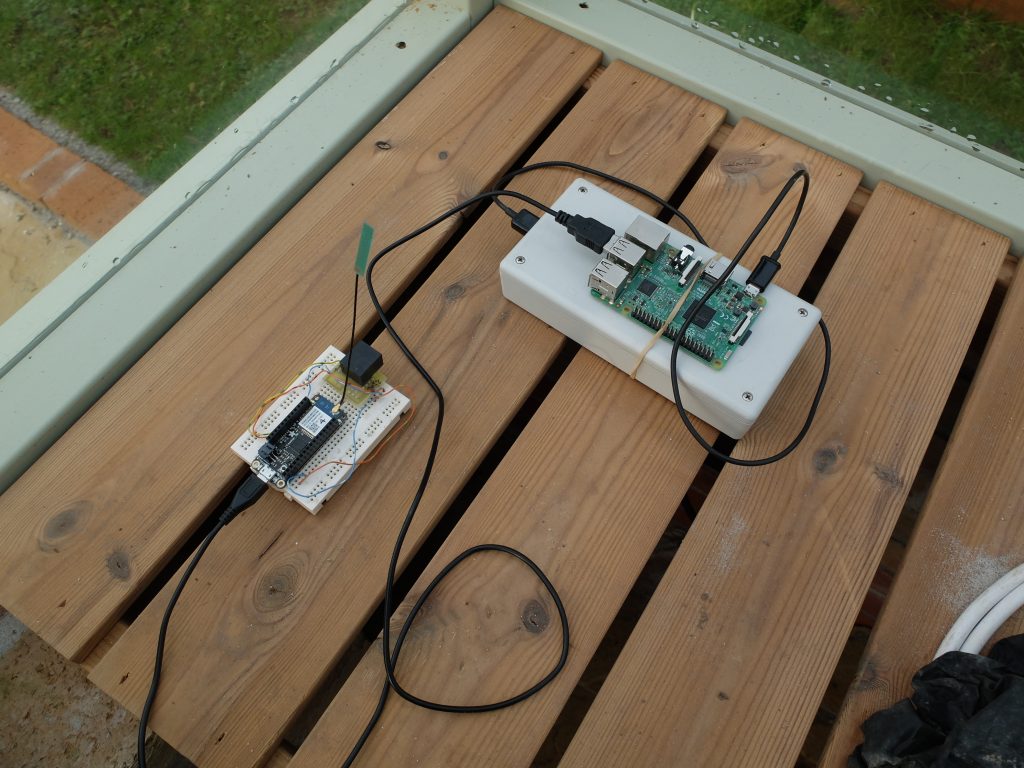
The picture shows a Raspberry Pi connected to an Adafruit Feather (on a breadboard) powered by a battery pack. (It all looks so simple at this stage!)
Design
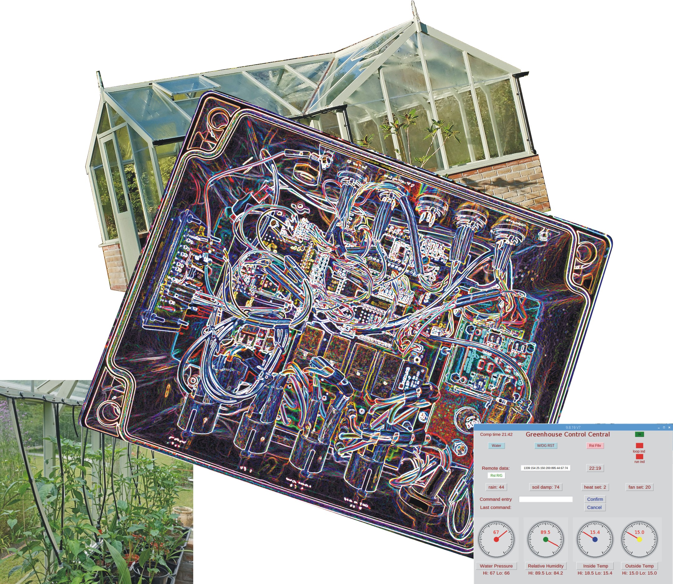
The next step was to write out a rough specification for the system. It would need to monitor temperature and soil moisture content and turn on a heater and a watering system. I might also add some weather station type facilities such as rain and sunshine gauges.
The “outputs” will be handled by mains switching relays rated at 16 amps (although the total load will be restricted to 13 amps). This requires some reasonably heavy duty wiring, plugs and sockets etc which inevitably takes up quite a bit of space.
The “inputs” will be I2C temperature sensors, some soil moisture sensors (of my own design ) And a few other types as noted above. These need plugs and sockets which again take up space. I took a guess, on past experience, that I could fit the Feather, relays, drivers etc onto a 160 x 100 mm pcb board and get this, a 5 volt power supply, a Raspberry Pi and the various plugs and sockets into a box 220 x 190 x 100 mm.
With regard to I2C, I know this is intended for short connections within a piece of equipment but I have used it perfectly well over distances of 10 m or more which should be adequate for what I have in mind.
One other thing I need to be aware of is the possibility of moisture getting into the equipment or the connections. The greenhouse is nominally watertight but slight leaks can occur, there is condensation and, of course, stuff gets watered in a greenhouse!
Block Diagram of Circuit
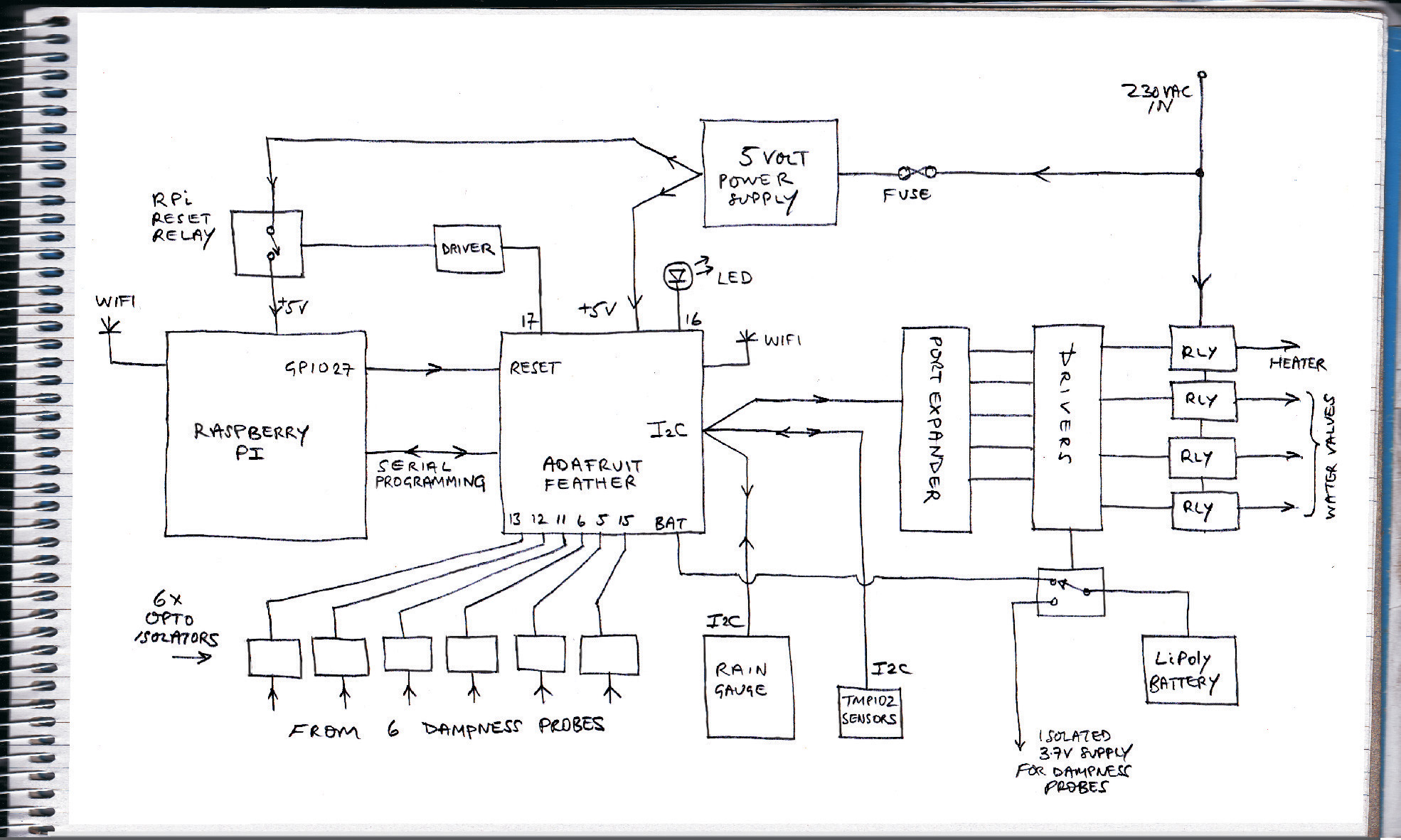
General Description
The Rpi and the Feather are connected by a serial/usb programming lead and a direct connection (via a buffering transistor) between GPIO 27 and the reset pin on the Feather. Thus the Rpi can reset the Feather if it crashes. The Feather also receives its power via the usb programming lead.
The Feather can restart the Pi if it has been shutdown (or crashed) as the power supply to the Pi can be interrupted by a relay operated by the Feather. If the Pi is shutdown, power to the usb ports is turned off which would shutdown the Feather were it not for its battery which automatically kicks in when power is lost. (This would fine, however, I later found that I needed to power-off reset the Feather following programming rather than just pulling the reset pin low. This, according to Adafruit, should not be needed so it might be faulty programming on my part. Anyway, I go into this in more detail later.)
The relays controlling mains powered systems (heater, fan, water valves) are switched by a MCP23017 port expander which talks to the Feather by I2C.
Temperature sensors comprising TMP102 I2C sensors are also linked to the Feather’s I2C bus.
My dampness sensors connect to individual digital inputs on the Feather via opto-isolators. The sensors produce a train of pulses the repetition frequency of which relates to the dampness in the soil being measured. The Feather measures these rates. The sensors involve probes in the soil and it is probably not a good idea to randomly earth microprocessors where all sorts of unwanted current loops could affect matters. Hence the opto-isolators. An isolated power supply to these sensors is provided by the Lipoly battery which is switched out of the Feather supply, when required, by a two pole relay. I still need to determine whether I can get away with energising all the sensors simultaneously for reasons I will go into later.
The Feather is supplemented by a “Adalogger” “Feather Wing” which adds SD card data storage and a real time clock.
Circuit Diagram of the Feather Section
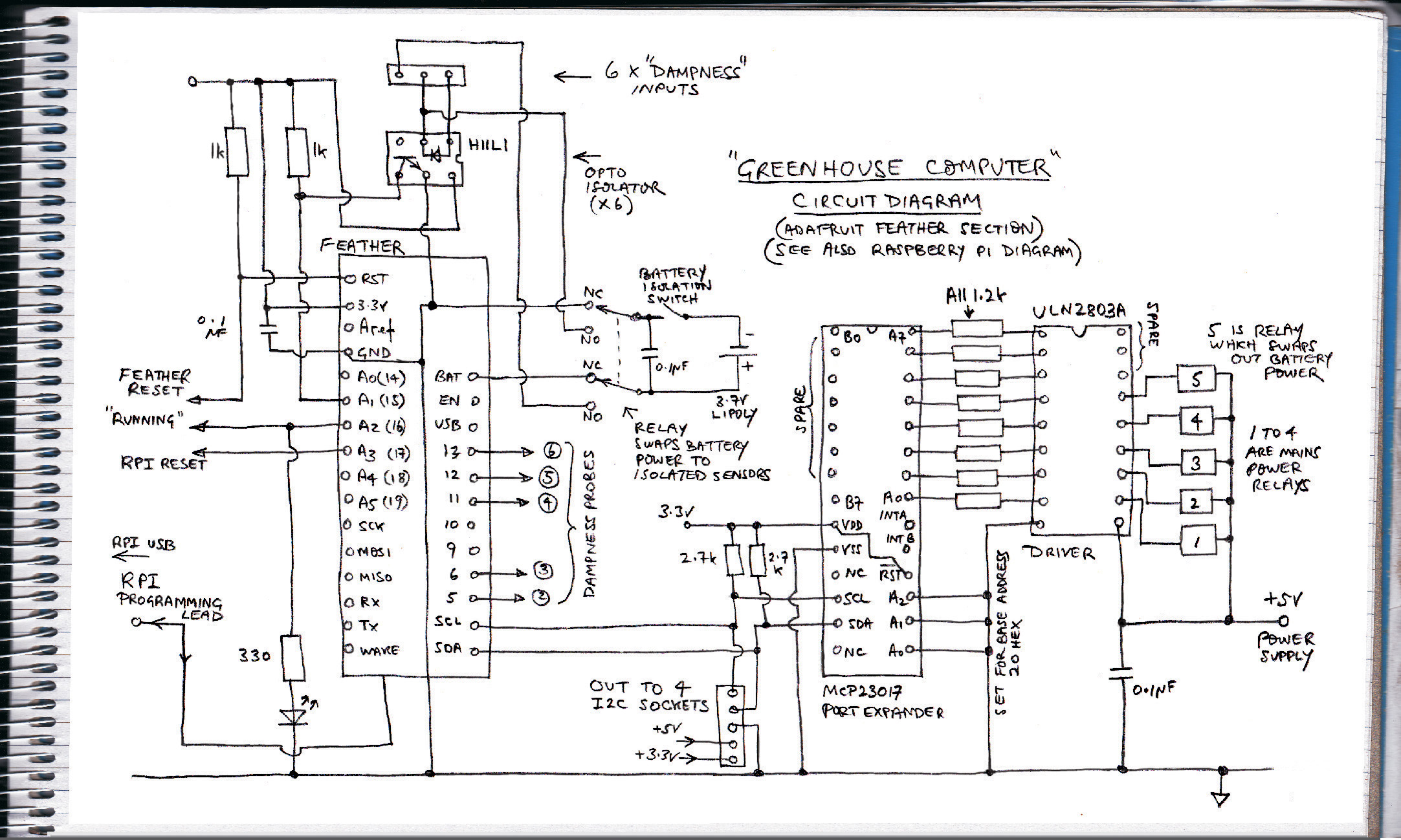
Descripion of the Circuit
The five relays are switched via MCP23017 port expander which communicates with the Feather over I2C. This leaves a lot of inputs/outputs spare (for possible future development). There is an Adafruit library for the Arduino/Feather etc which enables the expander pins to be addressed just like the pins on the processor itself and that makes programming very easy. (Also by wiring up the expander’s three address pins either to zero or 3.3 volts on the Feather – or 5 volts on the Arduino Uno – you could have up to eight expanders connected.) The outputs from the expander are not strong enough to drive the relays dirctly so they are boosted by a Darlington transistor array (ULN3803A) working at 5 volts (the Feather works at 3.3 volts, of course).
Six of the Feather’s own GPIO pins I connect to dampness sensors, one to an LED which I program to flash periodically so I can check at a glance that the Feather has not crashed. This pin also gets connected to the Raspberry Pi so that it can monitor that the Feather is running. Another pin is used to disconnect the power on the Raspberry Pi if it has been shut down (as this is the only way of restarting it). The Feather reset pin is connected to the Pi so that the Feather can be remotely reset.
After taking into consideration the use of some Feather pins by the Feather “Adalogger” board which sits on top of the Feather, that leaves three spare pins for possible future use.
Of the five relays mentioned above, one will be used to control a heater, three to control water valves for irrigation and one to power up the dampness monitors. As mentioned before, I want these to be electrically isolated from the main circuit. I will do this using opto-isolators on the inputs to the Feather and providing power to the sensor circuits themselves, the other side of the isolators as it were, using a battery. Helpfully, the Feather has the facility to run off a Lipoly battery and charge the battery up when the Feather is connected to an external source of power. The relay switches the battery out of the Feather circuit and into the sensor circuits when a measurement is being taken.
The external source of power referred to above comes via the programming lead (usb lead) which connects to the Raspberry Pi. The Pi needs to be active for 5 volts to be present on its usb ports. If it is shut down, power is cut off. If this happens, of course, the Feather will run until its battery runs flat (unless it tries to take a dampness reading in which case it will turn itself off, the relay will release and the Feather will reboot – the software will have to take account of this).
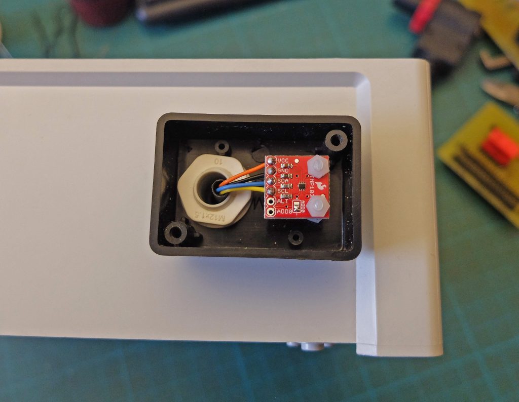
The I2C connection is taken out to four sockets. One is taken up by an internal temperature sensor (TMP102) which is fitted into a small box fitted to the outside of the main case to minimise the heating effect of the other circuitry. I expect other connections to involve an external temperature sensor and a rain gauge.
Circuit Diagram of the Raspberry Pi Section
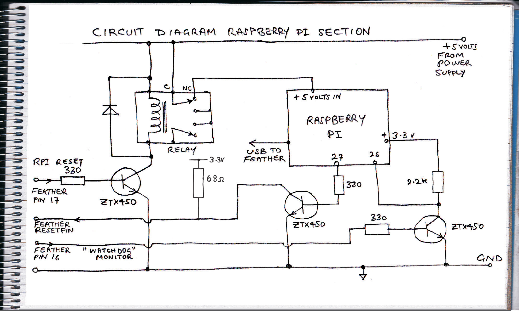
Description of the Circuit
The Raspberry Pi section is simpler. As mentioned above, its power supply comes via relay contacts so it can be disconnected to reset it following a shutdown. The relay is driven by a ZTX450 general purpose transistor or similar. Pin 27 (Broadcom numbering) connects to the Feather reset pin via another ZTX450 acting as a buffer (this feature has been deleted as explained later). The output of pin 16 on the Feather (pulses on and off to demonstrate the Feather is running and has not crashed) is connected to pin 26 on the Pi, again buffered by a ZTX450.
I think buffers should be used when pins on different processors are connected together. This prevents the case of both pins being set as outputs with one trying to go high and the other trying to go low. I’m not sure whether the outputs of the Pi and the Feather are proof against such contentions but it is better to be safe rather than sorry!
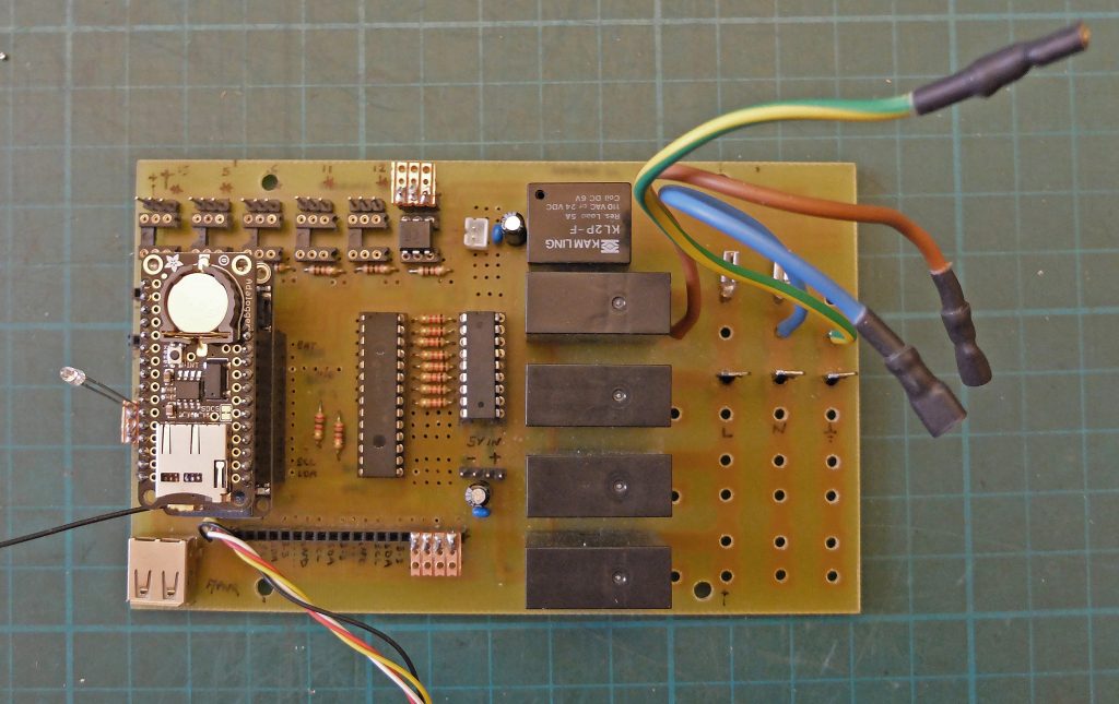
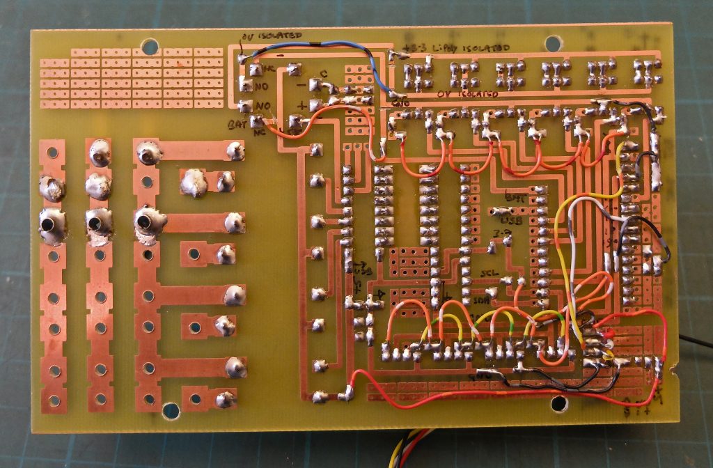
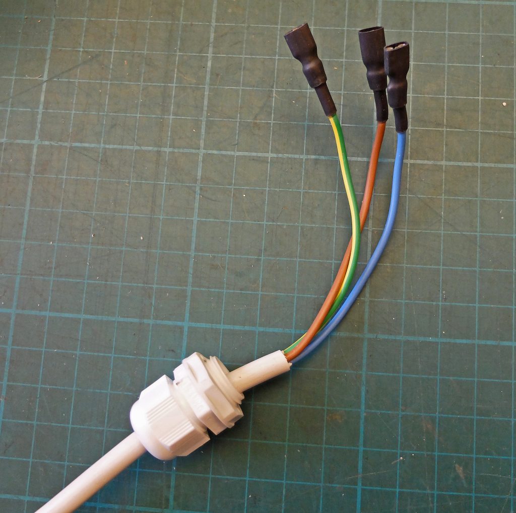
The first job is to design and make a pcb for the main circuit. I know from past experience that it will probably fit onto a piece of 100 x 160 material and so it proved! The circuit needed a fair number of links. On balance, I think the links are easier than making a double-sided board. The mains connections take up a fair amount of space and I have to allow for up to 13 amp capacity with plenty of margin (I hope). The mains comes in through 1/4 inch male spade connectors. The switched mains goes out to the sockets (“Cliffcon touch-proof”) via 3/16 inch female spades. This allows the pcb to be removed when required. I included some spare tracks for mods and corrected an error on the pcb with the battery polarity by cutting tracks and soldering wires (as usual!)
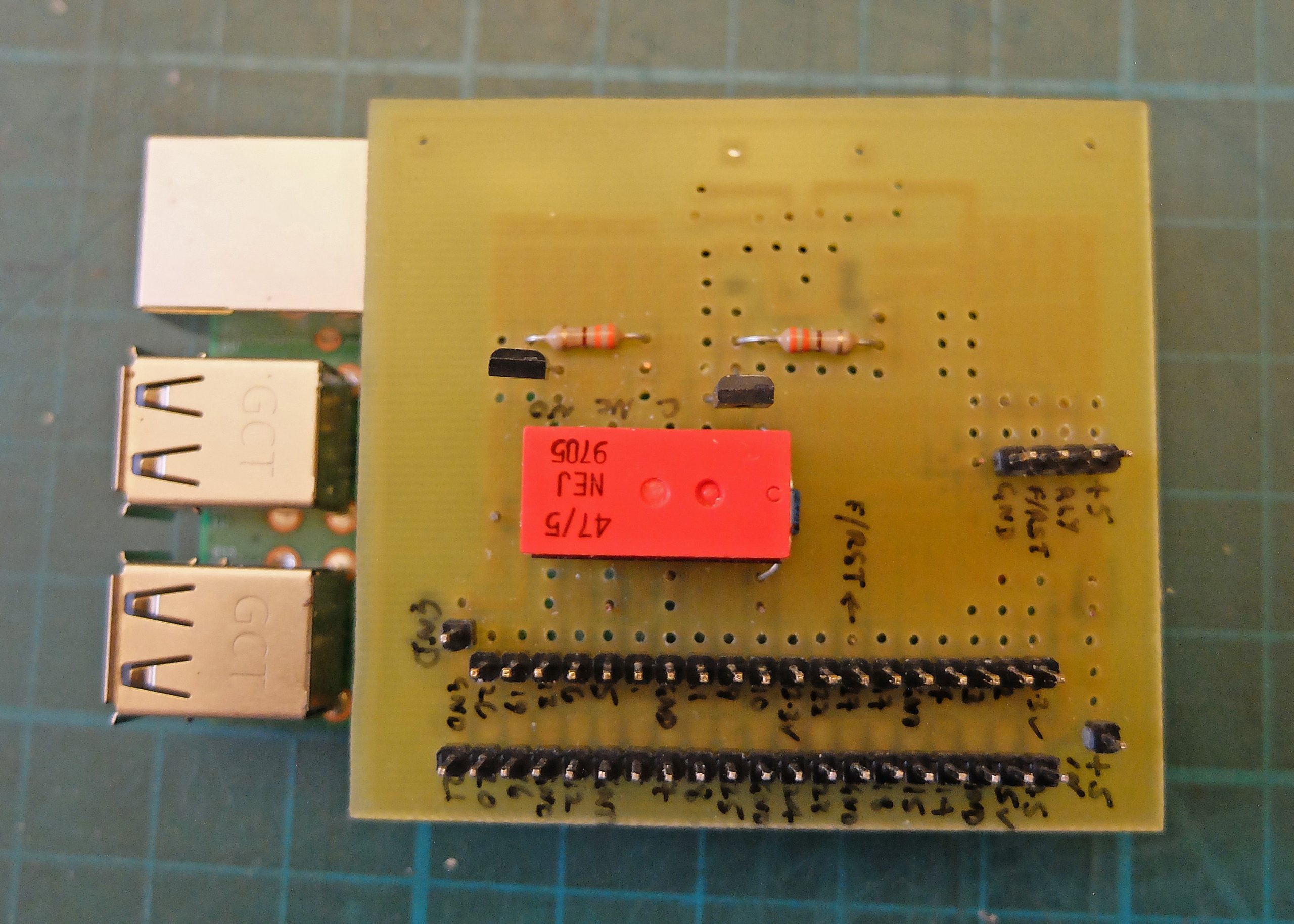
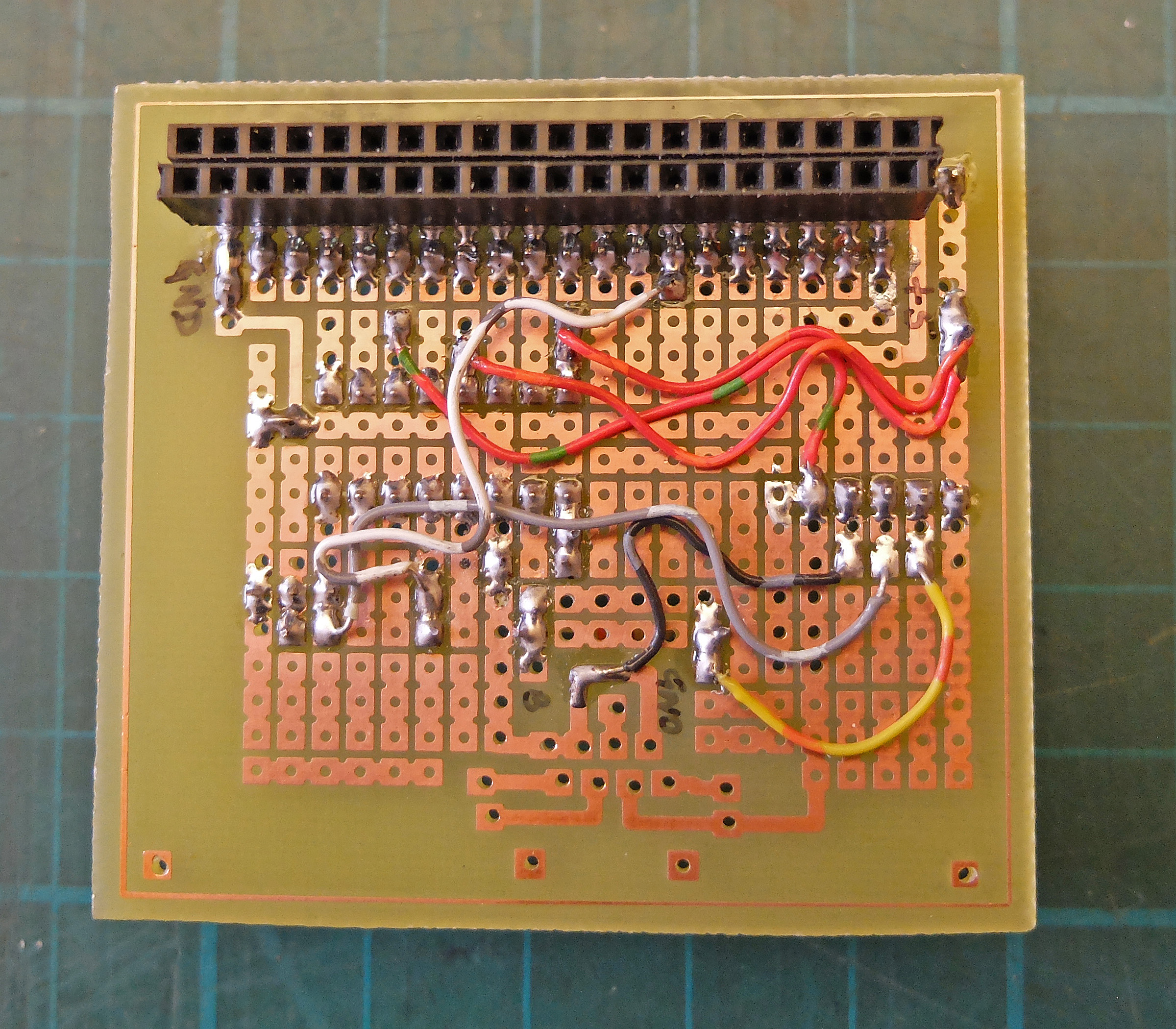
Above: This is the pcb for the Raspberry Pi (it’s plugged onto the Pi in the left pic). Here I used a pcb I had already designed for the Pi. The only problem is soldering the 40-way socket on the “wrong” side of the pcb. By not allowing the socket to pass all the way through the pcb, it is possible to get a soldering iron in at the side to solder the pins. (I feel it is a bit of a lash up but it works!) The pcb was a sort of “universal type” so, again, there were plenty of wires. (I use wires from bundles of twisted pairs from old telephone systems. These are ideal if you can get them. They have single-cored tinned conductors, lots of colours and insulation that is heat resisting. They are great for bread boards but too small to be reliable in, say, an Arduino’s sockets.)
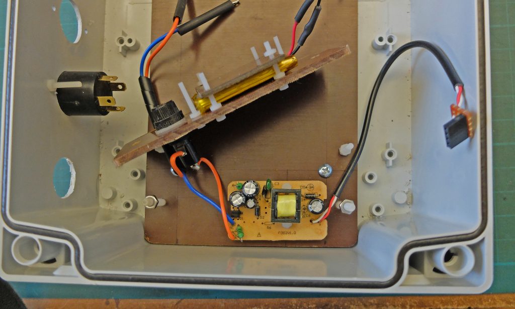
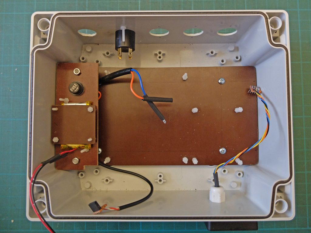
The picture on the left shows the power supply prised out of a “wall wart”. I have fitted a 20mm 200 mA fuse as the rest of the mains circuit is fused at 13 A. The supply is protected by a piece of Tufnol secured by nylon screws. The right picture shows the Tufnol base board that the other circuits are attached to again with nylon screws. The Lipoly battery sits on top of the power supply.
Above: This shows the unit with wiring still to do. Below, left: A tmp102 temperature unit (a Sparkfun breakout) is in its own box fixed to the main case by means of an adapted cable gland (in an attempt to insulate it from the heat generated by the unit. Later I abandoned this idea and used a remote sensor which combined temperature with relative humidity.) Below, right: 6.4 mm spade connectors used to connect the mains cable.
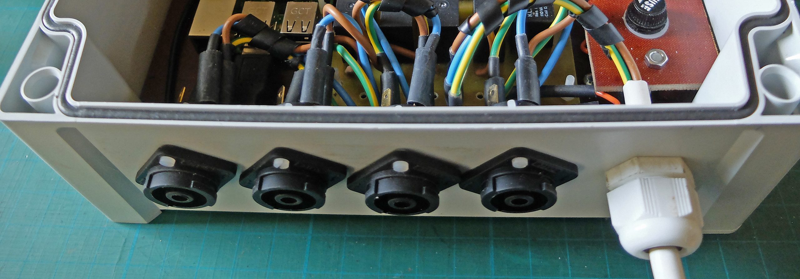
Below: Four Clifcon mains sockets from Rapid Electronics. These are nice and compact, touch-proof and rated at 26 amps.
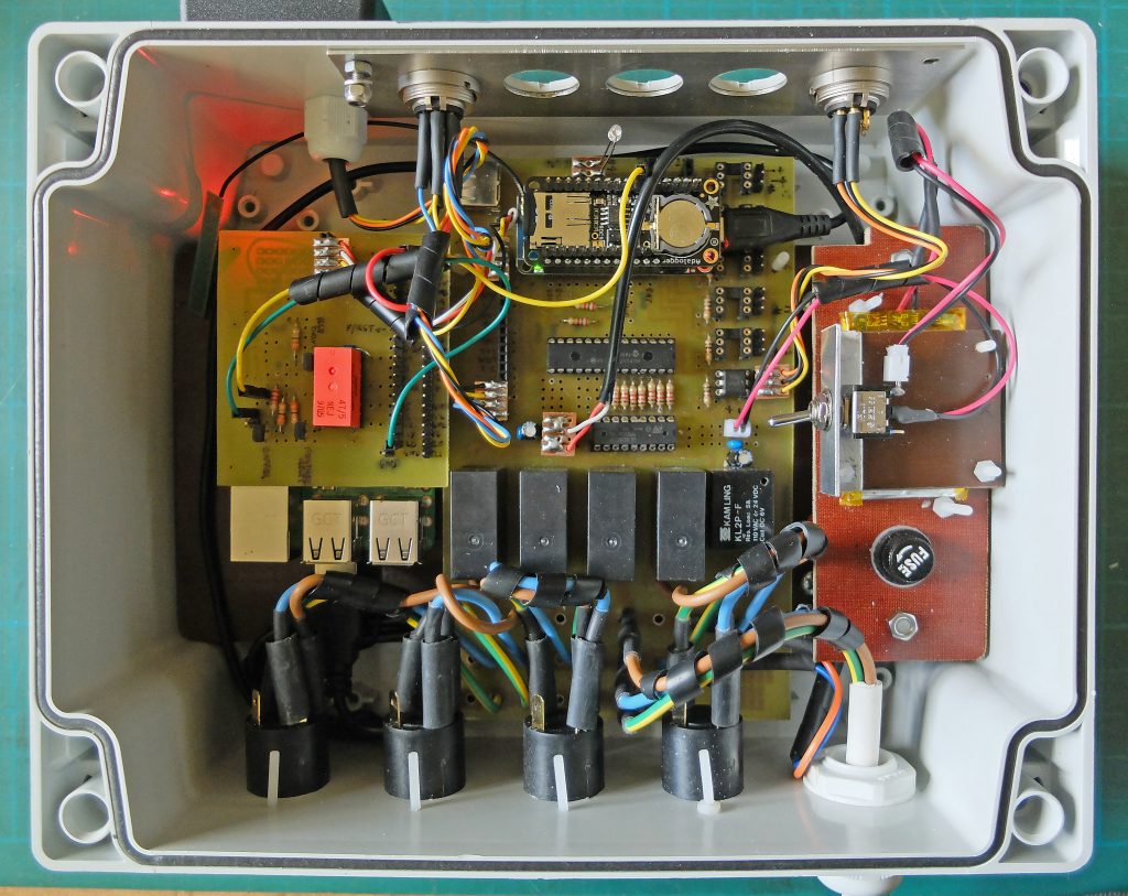
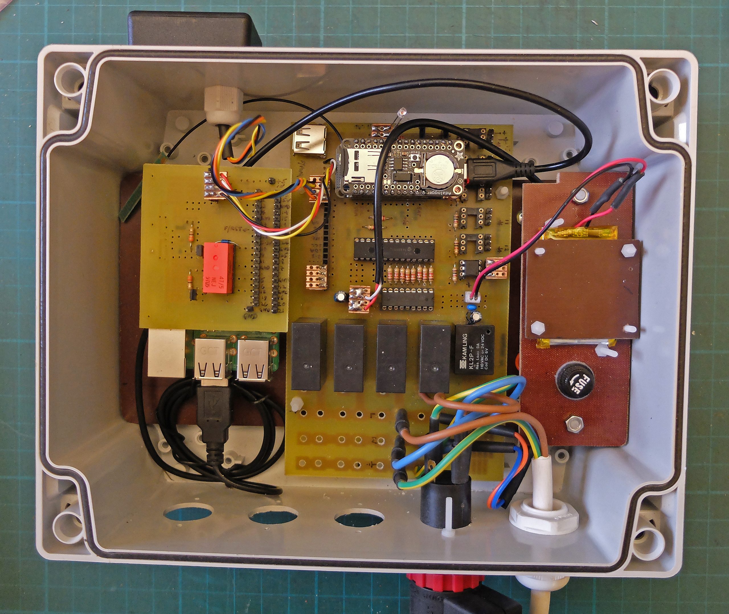
Above: This is the unit, as I thought at the time, essentially finished apart from three 5-way DIN sockets which I am using to connect the remote sensors. I have included an aluminium panel to earth the sockets if that is necessary. I included a switch to disconnect the battery when the unit is disconnected from the mains (or the Pi is shut down) to prevent the battery going flat.