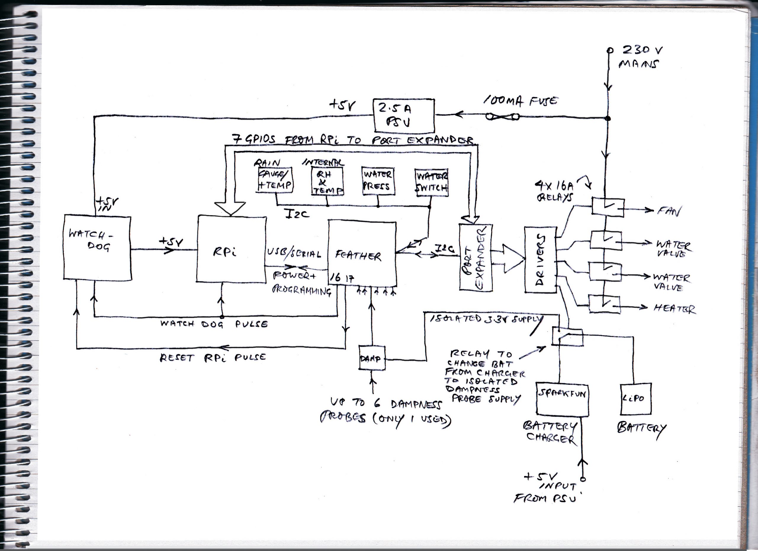
This, on the left is a screen shot taken from my PC showing the Raspberry Pi running in a VNC window. The Pi is running a test Python program which is interacting with the Feather controller over UDP. I chose to communicate between two computers only a couple of centimetres apart using UDP over wifi rather than, say, a direct serial connection, so that any other computer on the network could also participate if required. In another project linking a Pi and a Feather I used the serial/usb port to exchange data direct but that prevents the Serial Monitor facility being used. (In this project there is, of course, a serial connection between the Pi and the Feather which is used to program the Feather and receive data direct, if required, using the Serial Monitor facility. That ability, it turned out later, was very useful!)
At this early stage, the Python program does a few basic things. Later it will do a fair bit more, I hope! Firstly, it checks that the Feather program is running. The Feather turns an LED on and off as it runs through its main loop. A Pi GPIO pin is directly connected to this (via a ZTX450 transistor buffer). The red square (actually a button) flashes in sympathy.
The program counts the number of times this flashes in 30 seconds. If it is less than 15 times the label to the right of the red square indicates that, in the opinion of the program, the Feather is not running. If the “Auto Reset” facility has been enabled, the Pi will then reset the Feather by taking its reset pin to zero volts by means of a PI GPIO pin and a ZTX450 buffer. (This initially seemed to work but as will be described, there were problems!) There is also a button to reset the Feather manually. During development the Feather can crash and the reset facility is useful (remember, the Feather is in a box at the bottom of the garden!)
The program also shows some data from the Feather in a rather cryptic form including the time in minutes (the time is also shown in hours and minutes) and the temperature as measured by the TMP102 sensor (X10) and the thermostat setting (again X10).
Finally, a text based command can be entered which is transmitted to the Feather. Several commands are recognised and there is some validation included. The Feather recognises the command “reset” which causes the Feather to trip the relay which disconnects power to the Pi, if the Pi has been shut down. This is not allowed by the Python program (why would you want to reset the Pi if it were already running?) but can be sent by a remote computer if necessary. (Irritatingly, both the Pi and the Feather don’t seem to be able to run for long or even longish periods without crashing and steps need to be taken to automatically reset them if neccessary, it seems – see later.)
At this stge the Feather program logs into the local wifi and retrieves the preset temperature value for the thermostat function from the SD card. It decodes the time on its clock and allows the clock to be adjusted to the correct time. It accepts updates to the thermostat temperature and stores them on the SD card. It sends the status data noted above on request from the Python program. It also accepts various commands such as turning off the thermostat function and reverting to direct remote control of the heater. Of course, it measures the local temperature detrmined by the sensor and turns the heater on and off as required avoiding on/off “flutter” or “chatter”. At this stage, the system is not much more than a very complicated thermostat!
Further Development
The development of the hardware and software in this project has had some problems! One involves getting the Feather microprocessor to detect the presence of the WiFi module following the uploading of a new sketch. After uploading my sketch, WiFi.status() returns WL_NO_SHIELD. However, if the USB lead is removed, the LiPoly disconnected then the USB lead is replaced, the WiFi Shield is detected and the connection to the network can take place. Then everything works as it should until I try to upload again. This was the case with a Raspberry Pi 3 and a Raspberry Pi B+ but not it the Feather were programmed from a PC. On the face of it, a problem with the Raspberry Pi. I considered (and breadboarded) adding an electronic switch into the USB +5 volt power connection (using the MIC4422YN) but then I discovered a program called hub-ctrl (https://github.com/codazoda/hub-ctrl.c) which does the job from software. Then you can write a script to turn off the USB power, wait for a second, then turn it on again. This solves my problem of being able to get the Feather to recognise its own WiFi in a reasonably elegant way but still does not explain what is causing the problem in the first place. Once installed according to the instructions on Github, the following script turns the USB power on and off. This needs to be done after a sketch has been uploaded.
#!/bin/bash

  sudo ./hub-ctrl -h 1 -P 2 -p 0

  sleep 1

  sudo ./hub-ctrl -h 1 -P 2 -p 1
Use nano to create the script, save it under a suitable name like usb_onoff.sh. Then make it executable:
sudo chmod +x ./usb_onoff.sh
One odd thing is that although this worked fine with the Pi3 B+ it didn’t work on the Pi3 for some reason. (By the way, it doesn’t seem possible to control the USB ports individually, they are all on or all off.)
This reset does not work if the LiPoly battery is plugged into the Feather so I had to arrange a separate charger (from Sparkfun). In this new arrangement, I no longer needed a switch to isolate the battery so I deleted it.
This power-off reset is still not without problems, however. From time to time after such a reset, the RPi loses track of which USB port the Feather is connected to (it should be /dev/tty/ACM0). Either it choses the wrong port or no port at all. This matters because the Serial Monitor supplied on the Arduino IDE only works with the above mentioned port (as far as I can see). Sometimes the port can be reselected from the menu sometimes it is not listed. In this case, the RPi needs to be reset which is a pain. This site seems to suggest how ports for devices can be made persistent by writing and invoking a rules file but so far I have not tried this.
Power Supply Problems
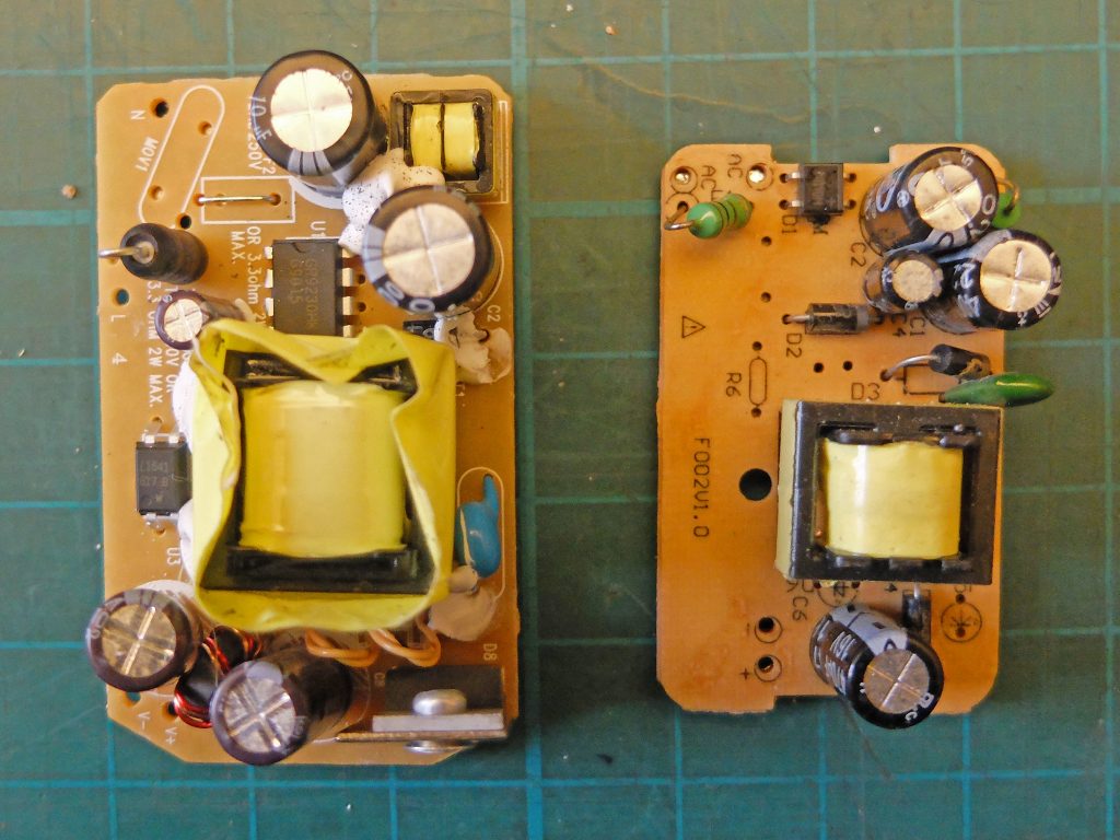
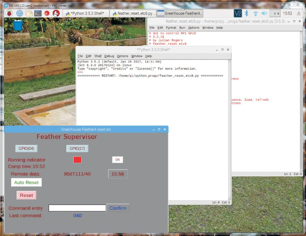
Above: These are the power supplies discussed in the text below. In each picture the “official” Rpi power supply is on the left and the eBay special on the right. Spot the difference! Output waveforms are shown later.
So, how did these problems manifest themselves? I noticed there could be a problem when the Pi3 B+ would not boot up when powered via a pin from the original (eBay special) power supply. Strangely, the Pi3 would boot up every time. It does turn out that the Pi3 B+ use a fair amount more power than the Pi3 but I don’t think simple brown outs were the problem. I looked at the power supply output on my BitScope and was rather surprised to see some voltage spikes of about 0.5 volts superimposed on the nominal 5 volts output. These may be the problem. I decided to replace the supply with one prised out of an “official” RPi power supply and was amazed by the difference in size (and apparent complexity – although this does not necessarily mean a lot) between the official supply and the original eBay purchase. The eBay supply was rated at 2 amps and the official supply at 2.5 amps but the difference in beefiness between the two was more than half an amp! I just can’t think why I didn’t notice that the supply was so weedy as I have seen quite a few in my time. Perhaps it’s the varifocal lenses in the glasses! (To be fair, a 2.5 amp supply has been recommended for the RPi for some time. It’s nearly always a mistake to be a cheapskate!) I should add that, to be fair, I have had some very good components from eBay. It’s not all bad by any means!
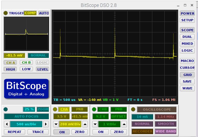
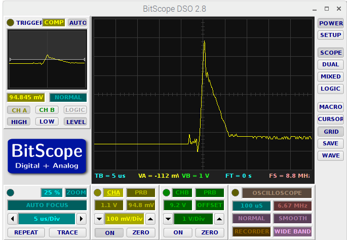

Above are traces showing the pulses superimposed on the output of the eBay power supply. They seem to occur about every 2.25 mSec. The right hand pic shows a pulse in more detail. The pic, left, shows the worst I could get out of the “official” power supply. (These were outputs on no load and do not take into consideration any noise or other artefacts introduced by the BitScope itself.)
Reset Pin Problems
The third problem involved the Feather reset pin. As noted above, I linked one of the RPi’s GPIO pins to the Feather reset pin via a transistor buffer so that the Pi could reset the Feather should it hang. I’m sure I have done a similar thing with an Arduino Uno where a hardware watchdog timer resets the processor if required. I just connected the collector of the transistor buffer to the reset pin as I assumed there was an internal resistor linked to (in the Uno case) +5 volts. In the case of the Feather, however, the impedance of the reset pin would seem to be very high as the Feather kept on resetting itself. A 1k resistor between reset and 3.3 volts improved matters but the Feather still reset on a very regular basis. I eventually reduced the value to 68 ohms. Most of the time this was stable but, from time to time, the Feather would still reset itself. Eventually I disconnected the reset from the RPi and the problem went away.
Perhaps the RPi GPIO pin is generating some positive spikes which trigger the reset but I can’t think why. As far as I know pin 27 is not committed to any other function than being a GPIO. If they happen, I imagine detecting them would be difficult with the equipment at my disposal. Anyway, as noted above, the problem has gone away. Anyway, resetting the Feather in this way seemed to leave it in a messed up state and not properly reset.
(Interim) Completion
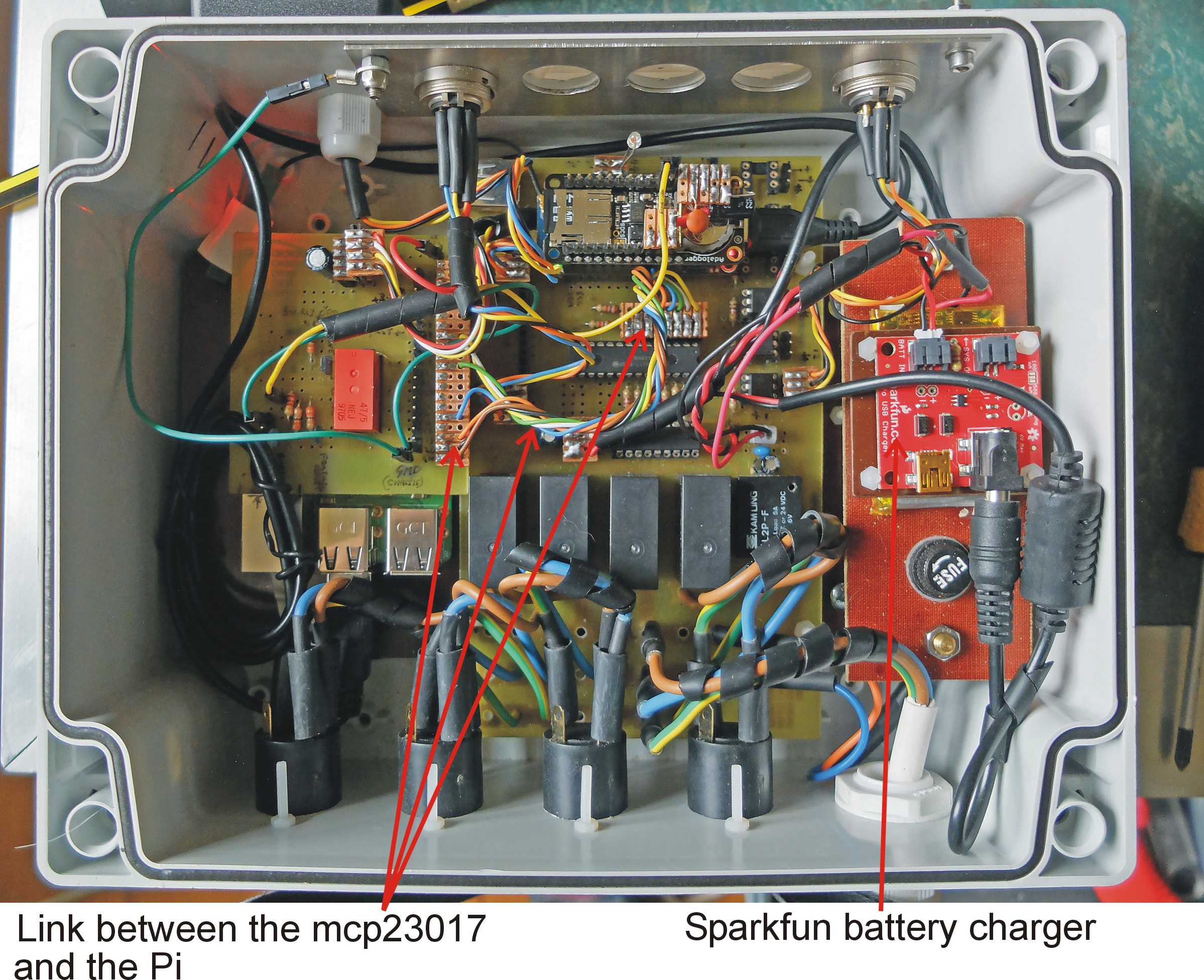
Below is the upgraded unit. The main change is the presence of the Sparkfun battery charger. The components on Veroboard plugged into the top of the Feather are decoupling capacitors which I threw in when I was concerned by the odd crash of the Raspberry Pi. I now believe these to be caused by the spikes produced by the power supply.
I also linked seven of the unused input/output pins on the mcp23017 with seven unused GPIO pins on the Rapberry Pi. I was slightly concerned about these connections as accidentally programming both ports as outputs and having one high and the other low might cause a blowout. As noted before, I had previously included transistor buffers which made such contentions impossible. So far, I have got away with it. The pins may have protection built in. So now I have possible communication between the Pi and the Feather by means of the serial/usb connection, these direct connections via the mcp2013 port expander and UDP via the WiFi which enables a considerable amout of flexibility in configuring the unit.
Talking about WiFi, I have had a number of connection problems between the Feather and the WiFi. With the WiFi booster/access point mentioned elsewhere, I was sure I had a strong signal in the vicinity of the Feather (my phone, tablet etc described the signal as strong and the Pi registered three out of four bars. However, the connection kept dropping out and the software on the Feather often registered only -84. Because of the contrary indications, I worried that the Feather WiFi module was faulty. However, eventually I tried re orientating the Feather’s antenna and saw an improvement. Later, I turned the control unit on its side and the signal increased dramatically to -70 or so (and the Pi registered 4 out of 4 bars). This seems to have cured a lot of the drop outs. However, over a period of time, there are still occasions when the Feather loses connection in a way not connected with signal strength. Lines on the Feather software have to be included to constantly check for connection and reset the WiFi if required. Because of the time taken in establishing a connection, this may lead to inadvertent triggering of the watchdog timer to be described shortly.
Cooling
During the long hot summer, the temperature in the greenhouse control unit reached a rather high temperature. Given that both the Raspberry Pi and the Feather were subject to crashing for no apparent reason, I began to suspect that the temperature might have something to do with it. So I devised an arrangement of two small fans in the lid, one blowing, the other sucking, to cool things down. The arrangement was thermostatically controlled using a slight modification to the arrangement I had used in my TR7 cooling system! This involved a TMP102 sensor, an Adafruit Trinket microprocessor and a MIC4221 driver for the fans, bits and pieces I already had lying around. (Later, I thought more about the crashes and it occurred to me that many happened at night when it was cooler. Also the crashes seemed to stop for no reason I could understand when I made some slight software changes. Nevertheless, I went ahead with the fans!)
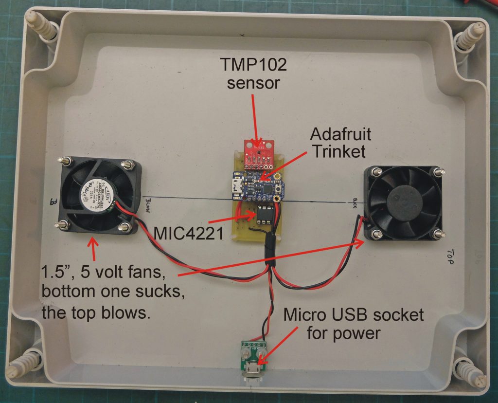
The picture left shows the main components. I bought the tiny fans a few years ago for an electronic humidor project which never happened. I decided that given the concerns I had about the capacity of the main power supply (see above) I would use an independent plug-in 5 volt supply for the fans.
Watchdog
As mentioned above, in the light of occasional crashes, I decided to install a hardware watchdog to reset the whole shooting match if necessary. This is very similar to the watchdog I made for the Adrduino-powered boiler programmer (coming soon to this site or see it on my old site, mr-r.co.uk). However, this time, the watchdog resets in the crudest way by cutting the power to the Raspberry Pi which in turn cuts the power to the Feather via the usb connection. In the Arduino version, the watchdog took the Arduino reset pin low. In this configuration, taking the Feather reset pin low does not seem to lead to a proper reset so that’s the reason for the method I have adopted. (You may remember that I included a relay to turn off power to the Rpi originally so I could start up the Pi remotely if I had inadvertently turned it off rather than resetting it via the Shutdown menu. The watchdog connects to this relay.)
S, to repeat myself, if you want a computer system to be reliable over a long period of time without supervision, my experience with the Arduino and similar processors together with Raspberry Pis, suggests that some form of device which will initiate a reset when things go wrong will be required. Computer crashes are caused by something but that something is mostly impossible to determine for someone like myself. There is too much going on in the libraries and firmware to comprehend when things fail at seemingly random intervals (maybe every few weeks).
I thought of using the Pi to monitor the Feather and reset it when it stops providing a regular pulse, indicating a crash. However, the Pi can itself crash so in the end I opted for an independent hardware solution.
There are some modifications to the previous circuit. Firstly, I increased the time between the last pulse being received from the Feather and reset to about 35 seconds to reduce the risk of false resets given that the Feather has much more to do in this application than the Arduino in the boiler programmer and may need more time to get round to sending out the pulse to indicate it is still running (I could probably use interrupts to get over this, something I must try). It seems rather difficult to get much more time than this. The timing is given by a capacitor charging though a resistor. A 100 microFarad capacitor with a resistor greater than about 270k supplied from 5 volts never gets to the 3.3 volts needed to end the timed period (I assume through losses in the capacitor).
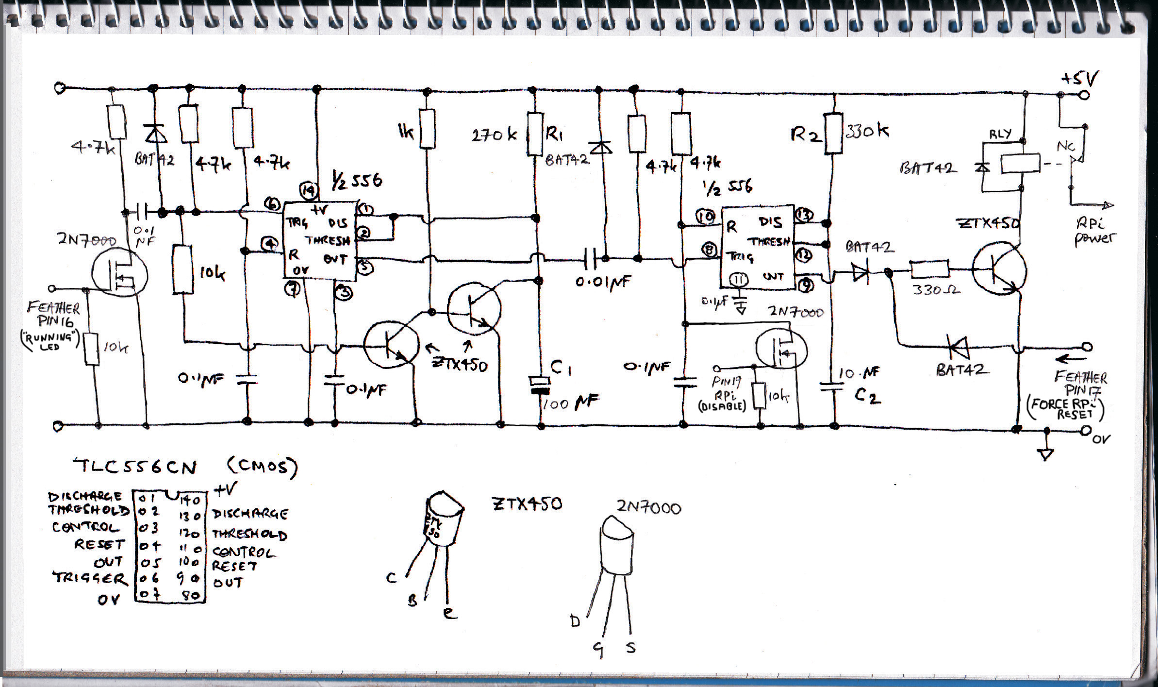
The transistor (2N7000) on the extreme left in the circuit above acts as a level shifter between the Feather which operates at 3.3 volts and the watchdog which operates at 5 volts. I have increased the coupling capacitor value between this transistor and the first 556 from 0.01 microfarads to 0.1 microfarads, otherwise the two ZT450s are not on long enough to keep the timing capacitor (which has been increased to 100 microfarads to give a longer delay) discharged. The second 2N7000 transistor is driven by a GPIO pin on the Rpi (pin 19). If the pin is high, the transistor is on and the second 556’s reset pin is shorted to ground, preventing the 556 from triggering and resetting the whole kit and caboodle. This could be required when a sketch is being uploaded which either delays producing the requisite pulses or is a sketch not designed to produce the pulses at all. Of course, as soon as the first 556 has completed its timed period the block on the second 556 will no longer be required (as long as there are no new trigger pulses to the first 556.
It would be possible to write a “suicide sketch” which issued one pulse to get the watchdog going but then stopped. This would result in the watchdog constantly resetting both the Feather and the Rpi. This would happen before the RPi could boot up and restore order. In this case the only solution would be to disconnect the watchdog (so without a lot more complexity, it couldn’t be done remotely!)
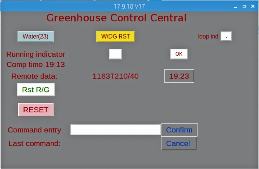
Left is a screenshot of the latest development of the Python program designed to supervise the Feather. The RESET button removes power to the usb port momentarily to reset the Feather following the uploading of a sketch which uses wifi (as previously described. The Water button turns on the watering facility for a period stored in the Feather’s sketch (currently 3 minutes. The Rst R/G button zeroes the file on the Feather’s SD card which stores the cumulative rainfall data since the last reset. The W/DG RST blocks the hardware watchdog as described above. More details of software will follow soon (hopefully)!
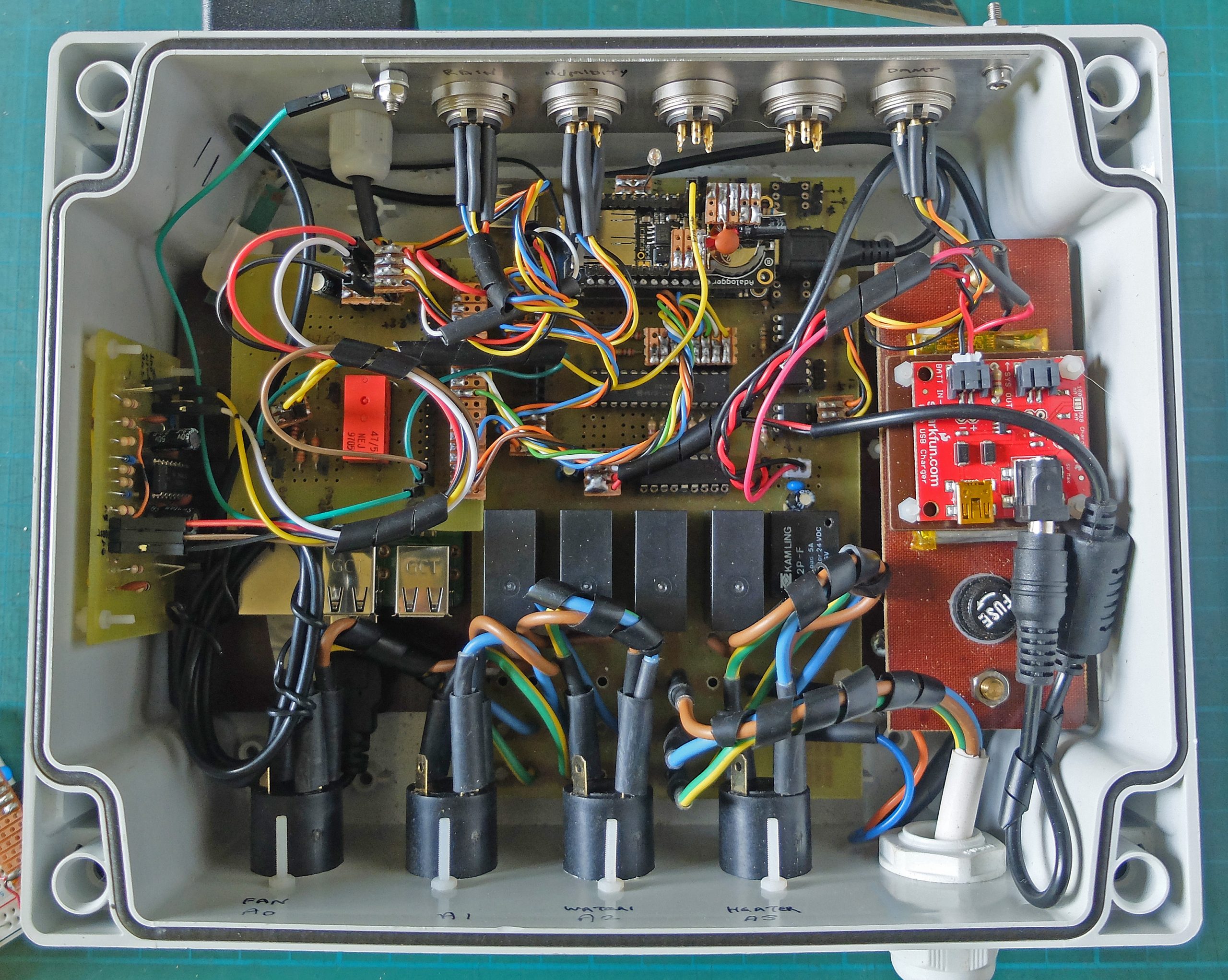
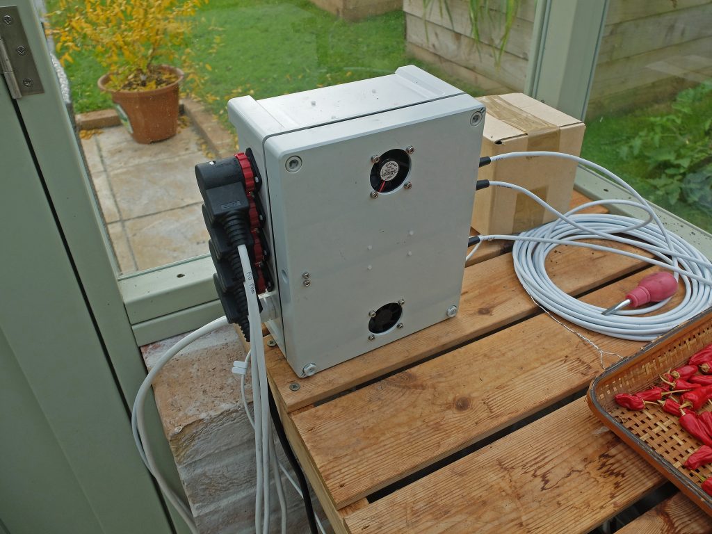
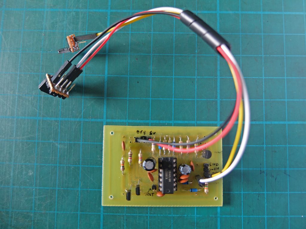
The picture above shows the final version of the hardware other than a couple of the DIN sockets (top) have not been wired in. The watchdog is screwed to the wall of the case on the left in the picture.
On another page I’ll describe some of the elements which will be plugged into the controller. These include, sensors and measuring devices: dampness monitor, inside and outside temperature, rainfall and water pressure to the automatic watering system. Relay switches for: automatic watering system, ventillation fan, and heater. And there will be details of the software for the Feather and the RPi.
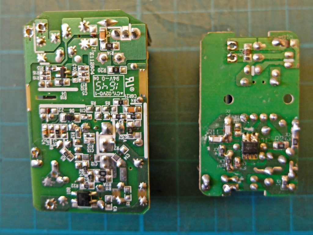
Below is the revised block diagram on the controller. The main changes over the original are removal of the battery backup to the Feather to facilitate clean resets, and the watchdog to prevent the Feather (which does nearly all the monitoring and control) from hanging up. There are also additional links from the RPi GPIOs to the Feather via the port expander and I2C. This gives more options for controlling the Feather by means of the RPi.