Introduction
In this project I am attempting to design and make a (reasonably) good looking and ergonomic soil dampness tester which could be used with pot plants and flower beds. I have previously made such a device but it fitted in a commercially available plastic box and, as such, was not very interesting to look at. So the focus here is very much on the 3D printing aspect although I will also run through the circuitry (which involves a micro computer and a miniature OLED display from Adafruit). Jump to electronics.
Design
I decided that the design would feature a pistol grip, which is probably as ergonomic as anything else. So I took a glue gun and drew round it on a piece of paper. I then scanned the drawing and loaded it into the vector-graphics program, CorelDraw 9. (If you had a tablet big enough you could skip the pencil work!) I have used this CorelDraw for many years and it works on Windows 10 and doesn’t require to be registered. The first version I had, CorelDraw 2 was very expensive, possibly more expensive than the latest version in real terms! However, the free program, Inkscape, will do just as well.
Transferring the design to 3D software
In order to get the 2D design to 3D, I take a rather roundabout route! First I export the CorelDraw (or Inkscape) drawing as a Windows metafile (WMF). I import this into Open Office Drawing and re export it as an SVG file. (If you are using Inkscape, although Inkscape can export an SVG file directly, this SVG file will not work in the next stage for some reason!) Next, import the WMF into Freecad (a free 3D design program of great power, apparently) and export it as a STEP file.
Finally, I import it into Design Spark Mechanical (a free 3D design program which is a cut down version of something quite expensive, I think) and extrude (pull) the various parts to give the 2D design the thickness required in the variou parts.
All the design work could be done on Freecad but this is a program I haven’t mastered (at all!). I like setting guide lines to various dimensions and snapping the elements of the design to these to get the required sizes. However, the dimension on Freecad are set by typing in constraints and this is not something I am familiar with and at my age, you tend to be a bit set in your ways. However, I have bought a how to book so…
2D design
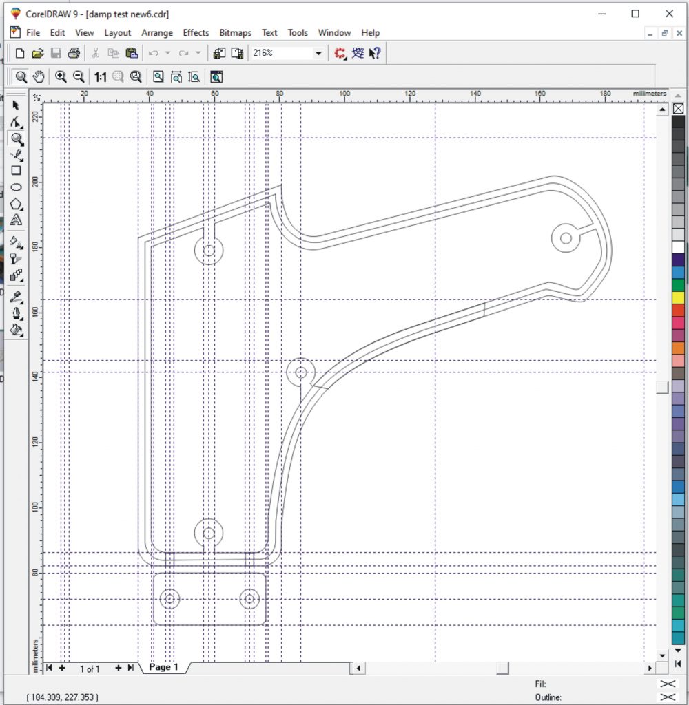
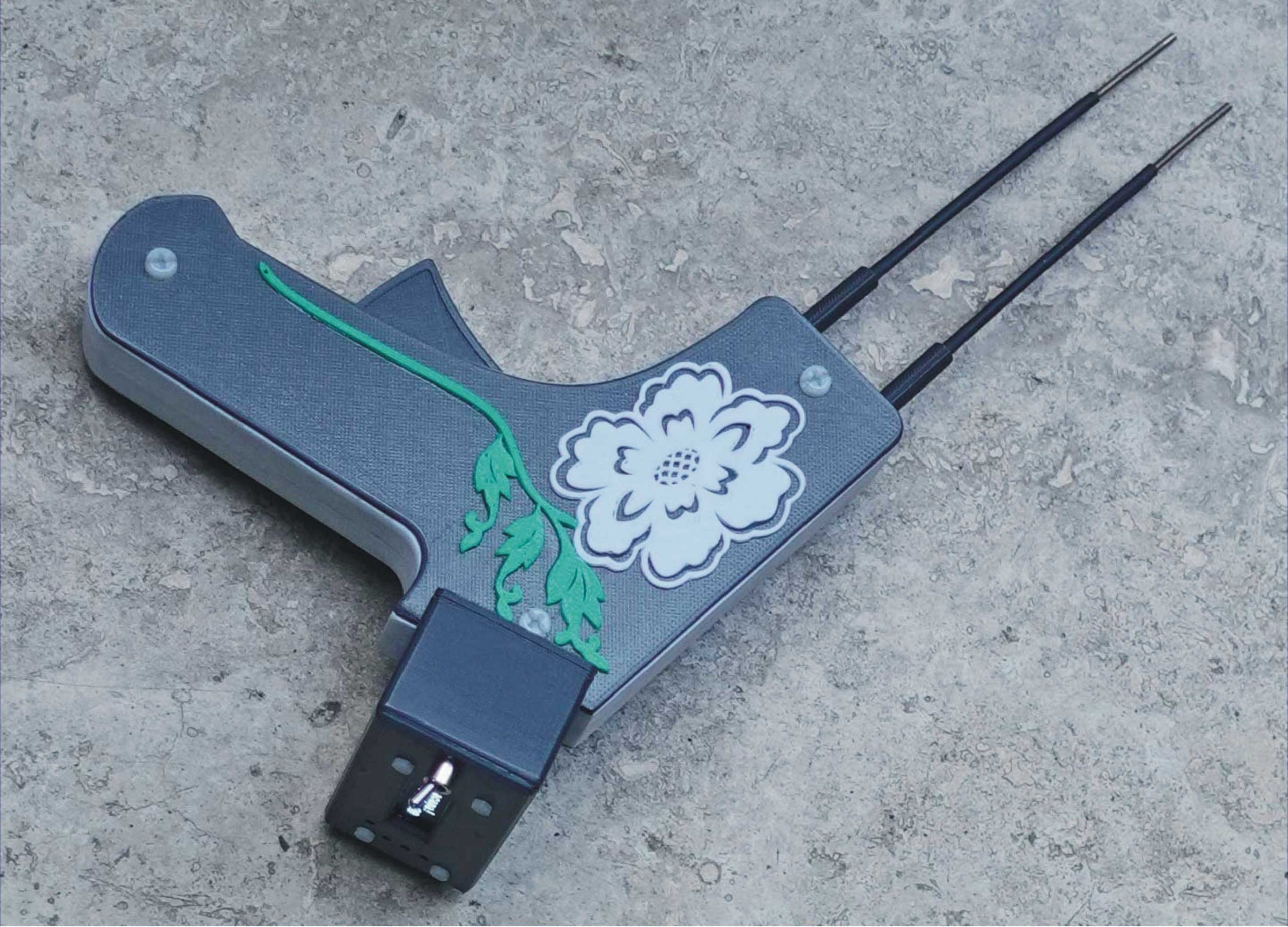
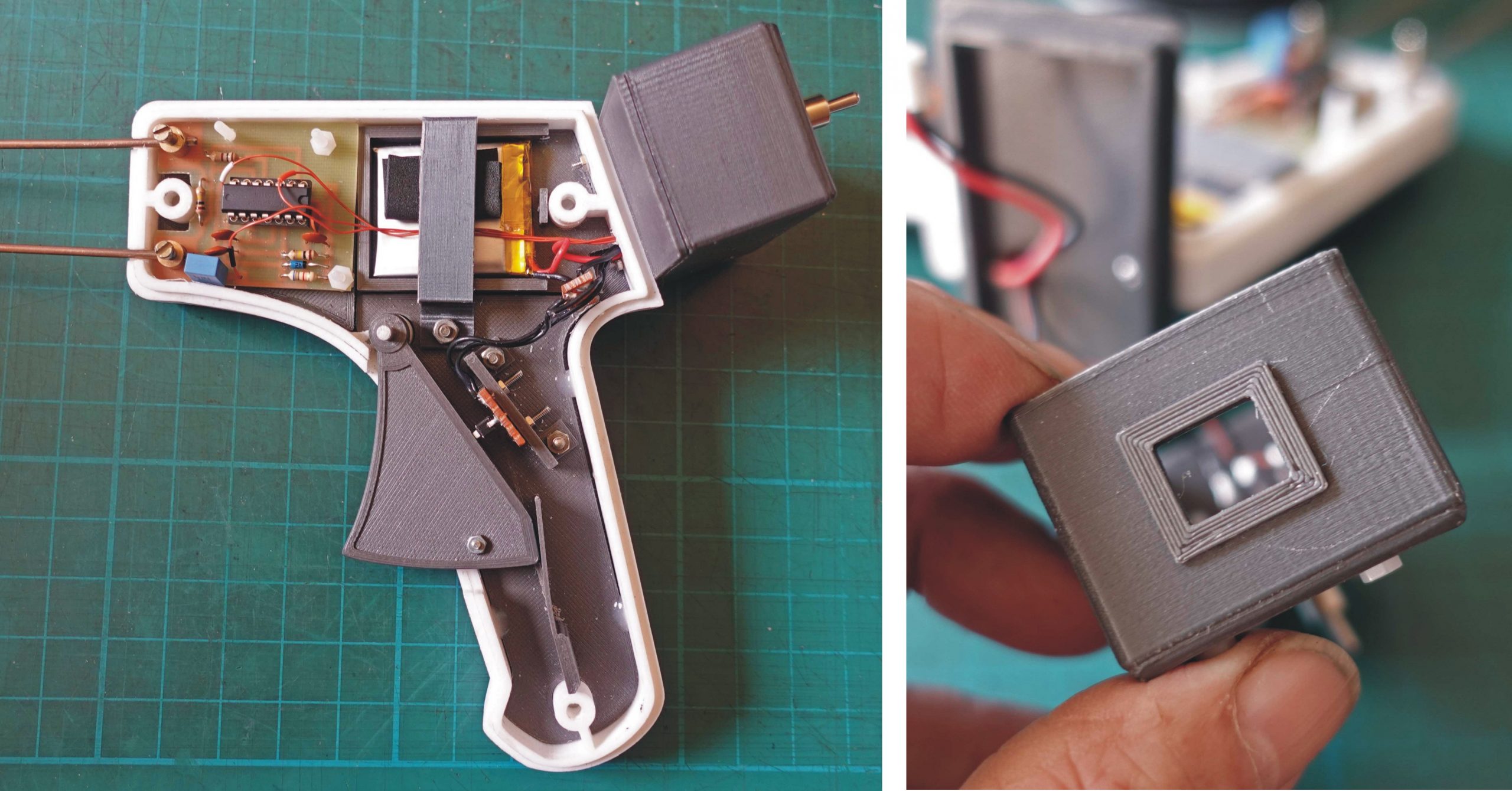
The picture shows the main part of the design for the project. The body of the unit is split in two round the edge and the two halves locate together by forming a step in the edge (see the 3D pictures below). The sides have to be printed separately as the bottom surface of a print is of low quality (at least on my printer). The assembly is fixed together by three M4 nylon screws which screw into the cylindrical extrusions on the side mouldings. The microprocessor (Adafruit Feather M0 and its OLED Feather Wing display) fits into a box which is fixed to the back of the pistol grip assembly. There are other parts which, amongst other things, support the measuring circuitry and the battery. I will describe them below.
3 dimensions
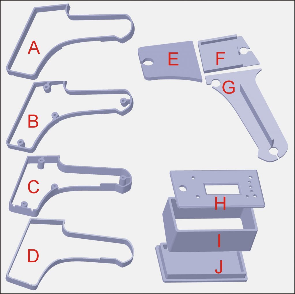
In the picture above, A and B are the two outer sections, B and C are the inner parts. Note the cut out for the trigger. Ideally, A and B would have been printed as one as would C and D. However, I decided to print the separately as I was not sure the dimensions would be right and I didn’t want to commit to a full print out (it takes hours and hours!). From one point of view, it was I good I took this course of action as my initial printouts were much too thick to hold comfortably and I ended up reducing each half to 10 mm depth. However, when I tried to glue the inner and the outer together, I found it very tricky (see later, below).
E, F an G are parts that form a sort of “chassis” that fits into C at the “bottom” – flush with the outer side when that is fitted. Having a chassis separate from the side means that screws will not show. The circuitry is screwed to E. F supports the LiPo battery and G supports the switch operated by the trigger. Note the “spring” printed on this piece. After printing, I used a fine saw to separate all but one end from the base so that it could act as a spring. Perhaps, you say, the plastic will fatigue over time and lose its springiness. Time will tell! Again, ideally, these would have been printed in one piece but because I had to test them as I went along, I printed them out separately to potentially save on printing if I needed to reprint anything.
H, I and J form a box for the Adafruit Feather and OLED Feather Wing. The front has to be printed separately to avoid the front being the bottom of the print. The back is a tight push fit into the box. This is fine at present. In the past, however, such push fits have relaxed a bit, possibly as the parts get a little hot in the sun, so I may have to add small screws later.
Manufacture
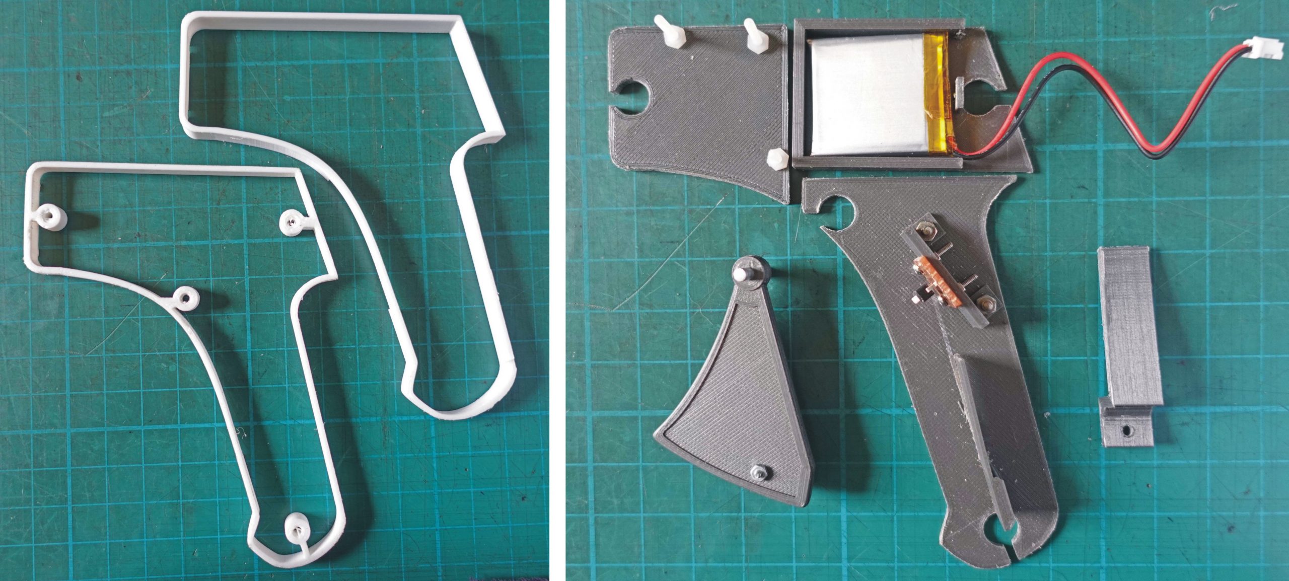
Above left shows parts C and D as manufactured. On the right are E, F and G plus the trigger, a clip to hold the battery in place and a bracket to hold a small tactile switch soldered onto a piece of strip board (Veroboard). On part E you can see the three M 2.5 nylon bolts which hold the pcb which contains the dampness detection circuitry (described later). The trigger is made in two halves to enable the frame effect to be on both sides (and again, hiding the bottom surface).
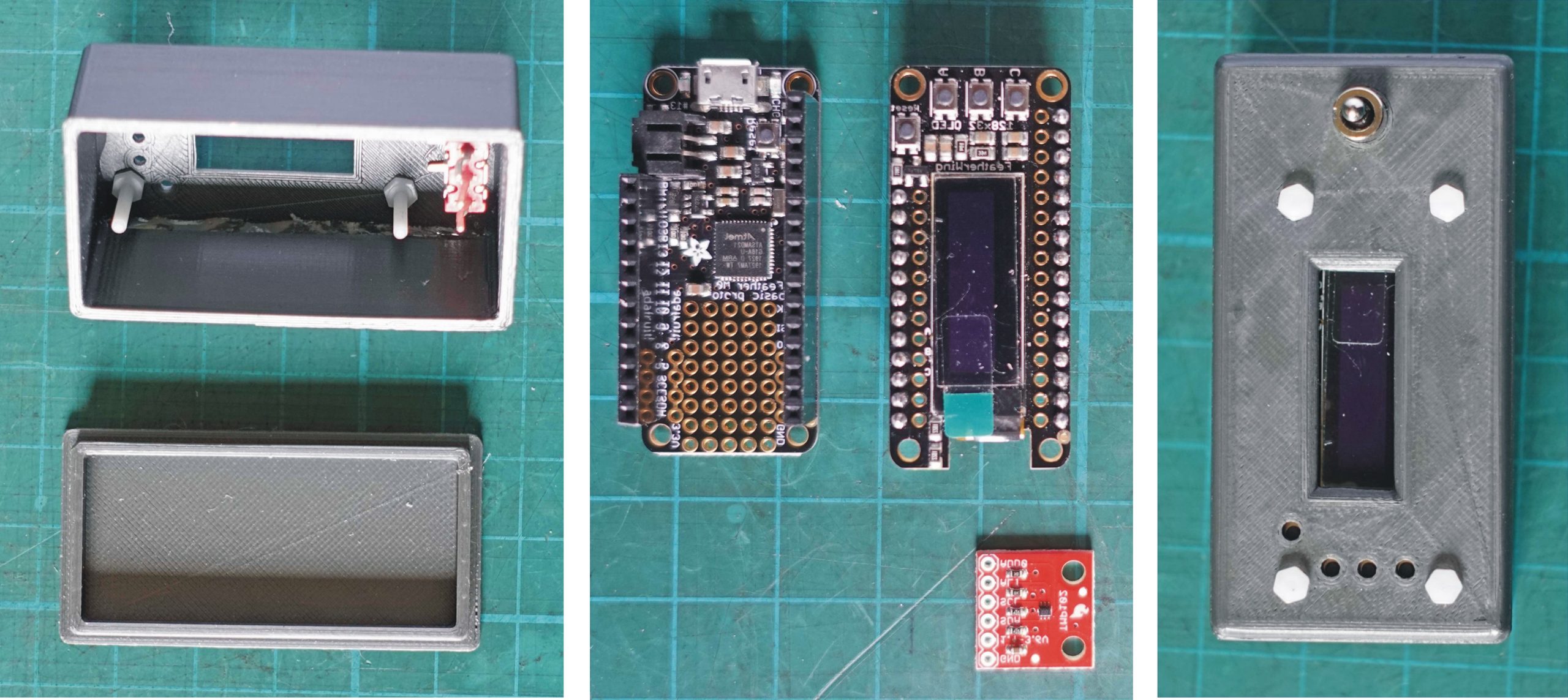
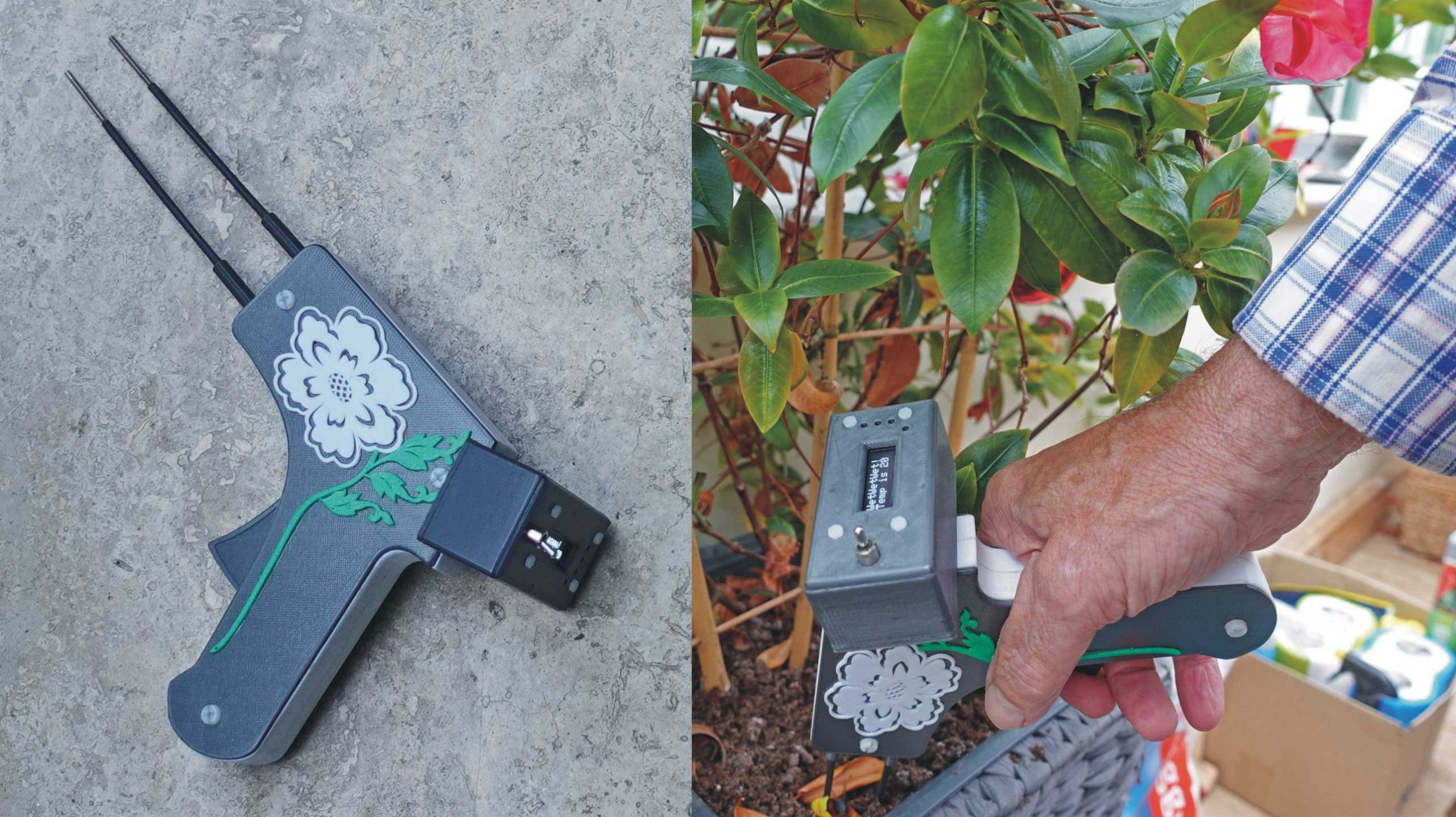
Above left: The case for the Adafruit Feather and OLED display with the front Araldited to the body. Centre: The Adafruit Feather Feather Wing OLED display and a TMP102 temperature sensor module (red pcb). Right: The front panel with a cut out for the display, a mode selector toggle switch and holes to clear the reset switch and three buttons provided on the OLED unit (but not used in this project). (If the holes are not present, the OLED cannot be mounted right against the panel.)
Making the probe clamps
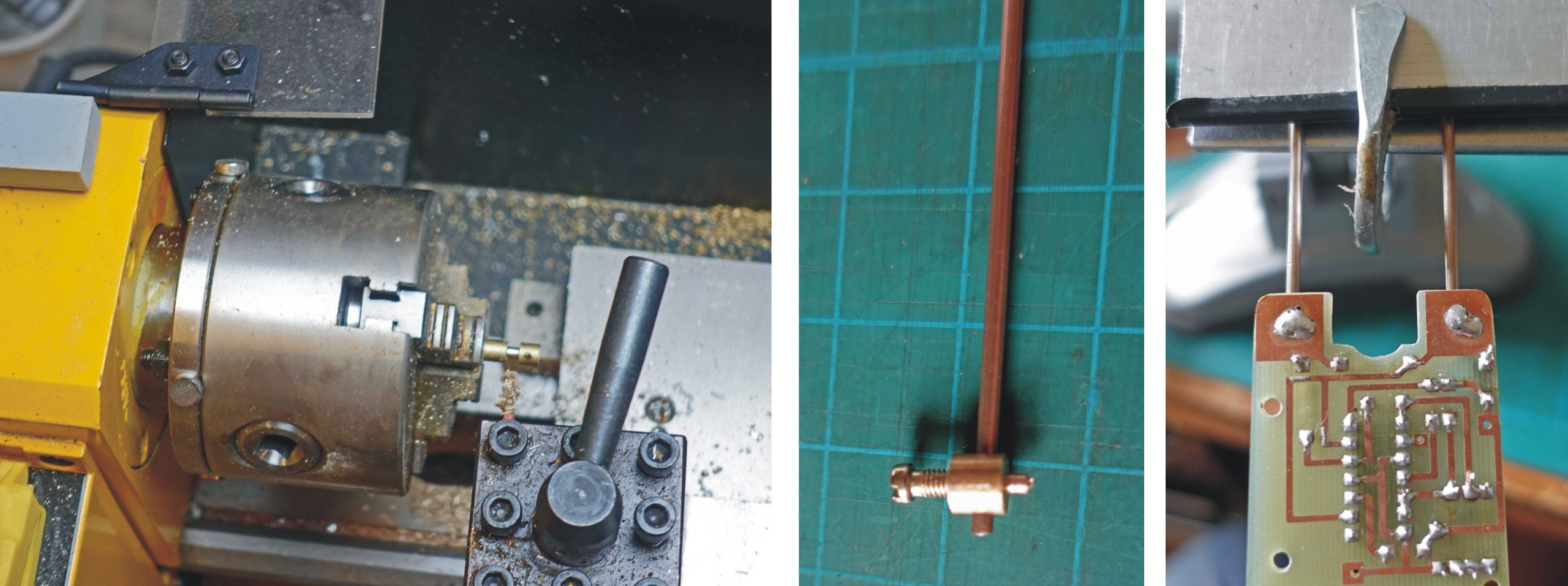
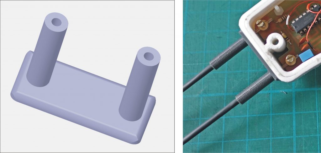
The probes are made from 2 mm brass rod. I would have used stainless steel welding rod if I had had some but brass is OK. The probes need to be clamped in place and electrically connected to the circuitry. In earlier versions, I used brass connectors extracted from connector strips/blocks soldered them to suitable pads on the main pcb, putting the components on top and the connectors on the bottom.
That arrangement would not fit conveniently in the present design so I made some new connectors turned from 6 mm brass rod (above, left) so they could fit on top of the pcb. The first job is to drill a 2.5 mm hole in the end of the rod on the lathe. Next remove the rod from the chuck, centre punch the hole for the probe, put the rod in a machine vice and drill a 2 mm hole positioning the rod in the drill press as carefully as possible so that the hole passes through the middle of the rod. At this point tap the grub screw hole to M 3. Replace the rod in the lathe and part down to about 1.5 mm diameter. Then part off the clamp leaving the nib 2 mm long.
Drill suitable holes in the pcb (details of that later), a tight fit is good. Fit the probes and clamp them parallel to each other and in the right position so that when the pcb is installed in the case, the probes point in the right direction. Use a reasonably powerful soldering iron to get the nib hot enough for the solder to flow (see picture above, right).
Assembly
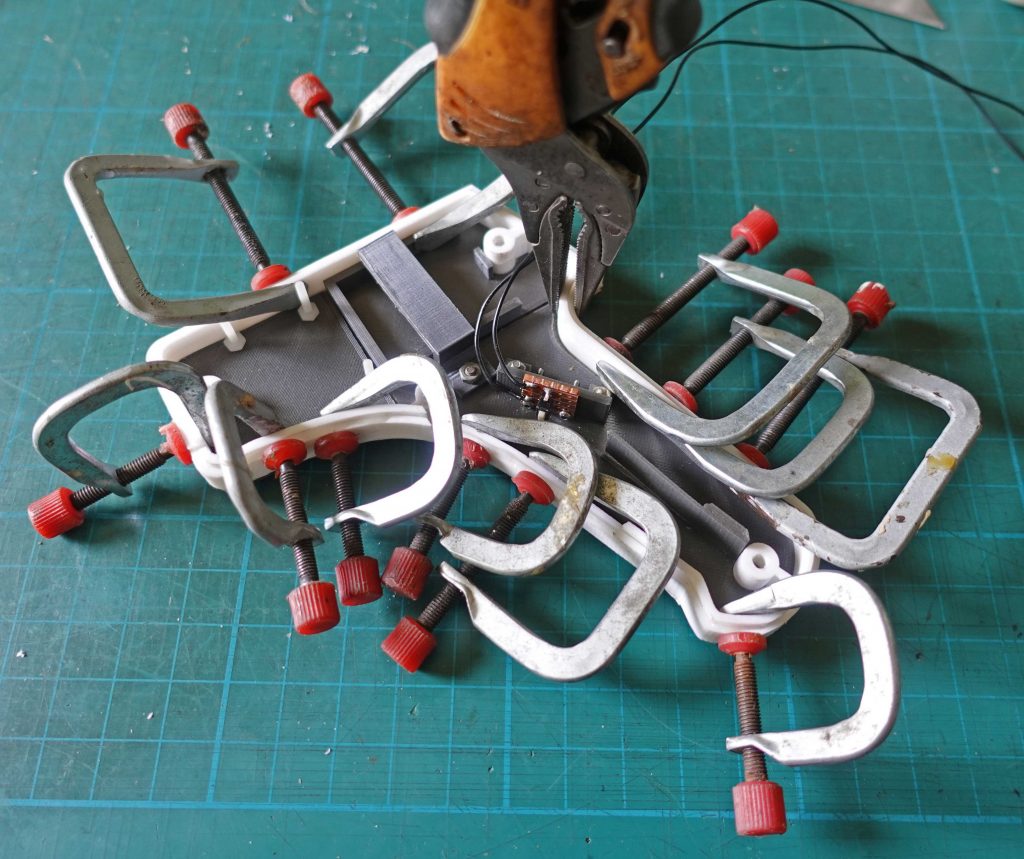
You may remember that I had made each of the two halves of the sides of the case themselves in two parts. The first job in assembling the project was to glue the inner and outer parts together. This was troublesome and were I to do it again, I would print the part out as one!
Firstly, getting the epoxy glue (Araldite) onto two parts which slide tightly together is always going to be a problem as the act of assembly scrapes the glue off. In the end I assembled the parts “dry” then prised them apart in stages and inserted the glue with a spatula. Then I used as many model-making G clamps as I could fit in. I also inserted the “chassis” parts mentioned above to make sure the clamps did not distort the assembly.
I scraped surplus glue away at the moment it became a firm-ish gel. This was reasonably successful but the clamping was a little uneven meaning that in places the two parts were not completely tight together. This will, however, not show once the side panels are in place.
The picture above, left shows the various components assembled into (half) the case. The “chassis” parts are secured with small blobs of Araldite which are just visible in the picture. The picture on the right shows the “window” through which the programming / charging lead is inserted. It was tricky to judge exactly where this would be at the design stage. So I resorted to fitting the Adafruit Feather etc. at which point I could measure the exact position required. I then drilled a hole and filed it big enough to take the USB lead. Since 3D printing generally is not set up to form a completely solid piece of plastic, such a hole has a messy and insubstantial edge. The answer was to print a little frame to finish off the hole which I Araldited in place.
To finish off the probes, I printed what amounts to two cylinders rising up from a flat plate. This was sized to fit over the probes. I fixed some heat-shrink tubing to the probes leaving 28 mm exposed at the business end to be exposed to the soil to be tested. Take the probes out of the unit to apply the heat-shrink as the heat gun used to shrink the tube would play havoc with the 3D printing! The probe finisher is held in place between the shrink-fit and the case and is not glued in place to make it easier to dismantle the unit if required.
Decoration
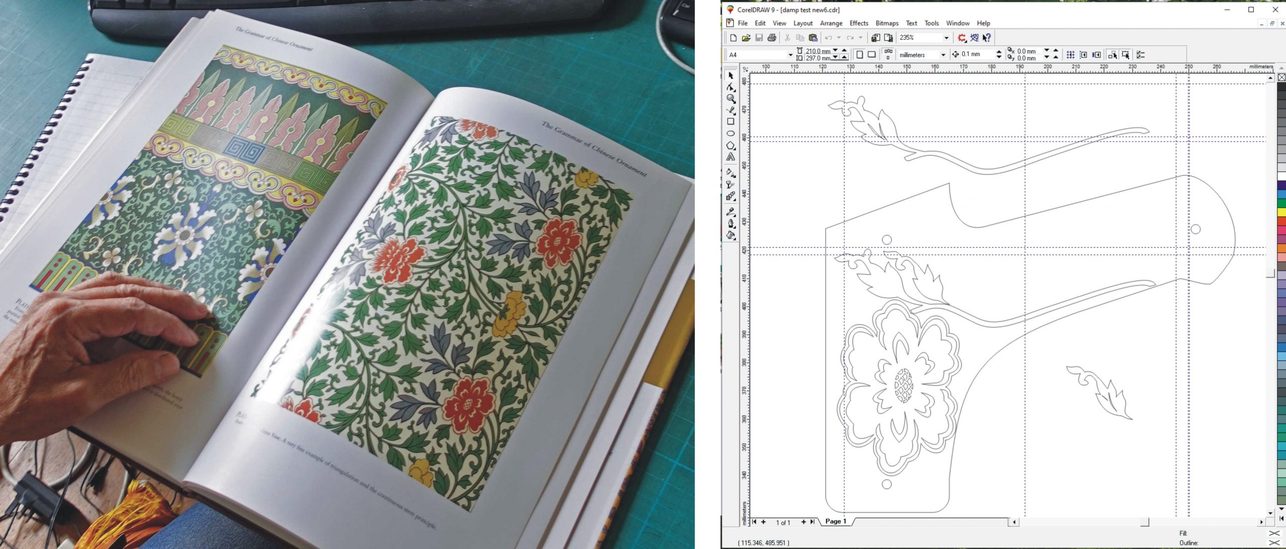
I thought the project needed a little decoration (if for no other reason than to make it look a little less like a stun gun!) Turning to a book of design motifs (The Grammar of Chinese Ornament by Owen Jones, above left), I scanned a page, loaded the image into CorelDraw and used the vector graphics facility to draw round a flower and some foliage (see picture above on the right). Then I went though the rigmarole outlined above to get it into a 3D printable form.
Gluing on the decoration
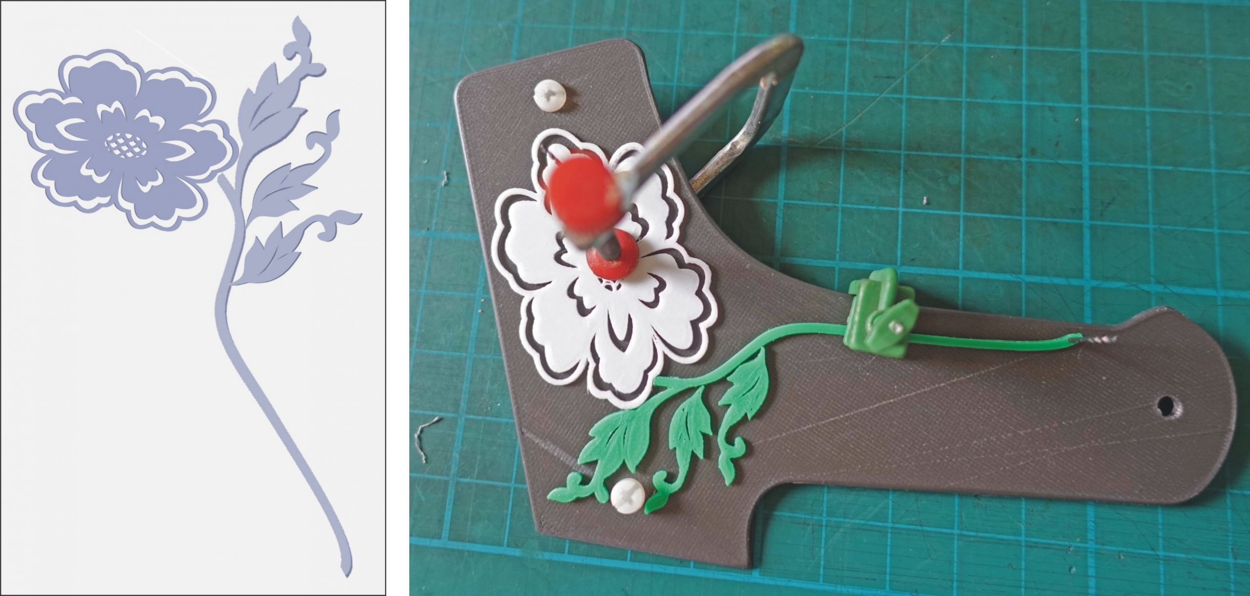
Above left: This picture shows the 3D design for the flower and foliage which was printed in four parts, the flower, the stem and leaf and two leaves. Next, I needed to be able to glue the decoration in the right place. With “wet” Araldite on the back of the decoration you only get one chance to place it in the correct position if you are to avoid smearing glue all over the place. So I needed a setup to locate the parts.
In the picture on the right, I have glued the stem and the flower together and am positioning them on the unit. I drilled a 1 mm hole in the end of the stem by means of a 1 mm bit in a pin vice. I drilled a corresponding hole in the side plate and, using a 1 mm drill bit as a pin, this enable one end of the flower/stem combination to be located. Then, I drilled another hole in the side plate to locate the other end. By this means, I was able to apply the glue to the decoration, get it in place and aooly sime clamps without any slippage.
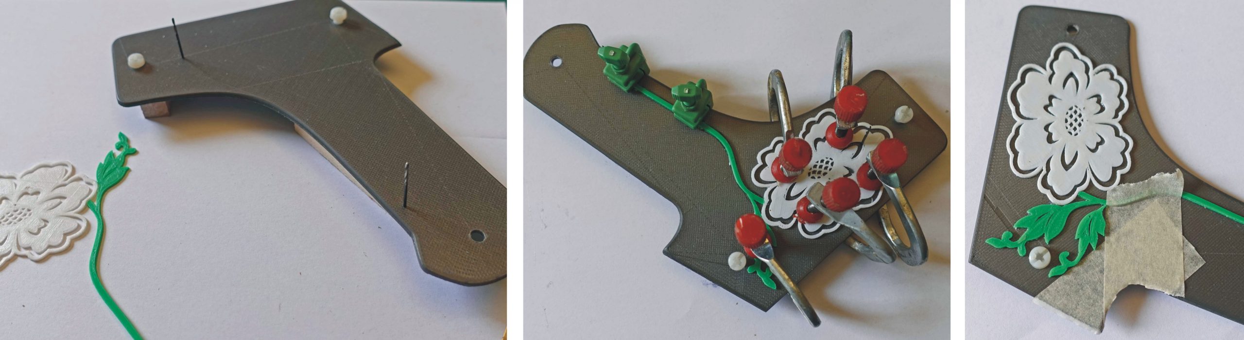
Above left: This picture shows the 1 mm drills used as location pins. Centre: The flower and stem are glued and clamped into position. Right: I used masking tape to locate the two individual leaves which were also glued and clamped into position. Again, I scraped away any surplus glue squeezed out when the glue had just gelled. Incidentally, you can see a blemish on the side panel in the 3D printing which sometimes inexplicably occurs. The other panel did not have this blemish although both used the same 2D drawing (one was just flipped to give the other hand). I can only assume these blemishes are caused by the Cura program which converts the STL file from the 3D design software into a file readable by the printer or perhaps it’s a bug in the printer software… who knows! These things happen and often the only way out is to draw the same part in a slightly different way and hope that works.