
Introduction
This project (probably!) completes my gas boiler control suite. There has been a timer driven by a WiFi enabled Arduino Uno, and a boiler temperature controller powered by two(!) Arduino Unos. In both cases they are controlled by a Raspberry Pi 4 running a Python/Tkinter program.
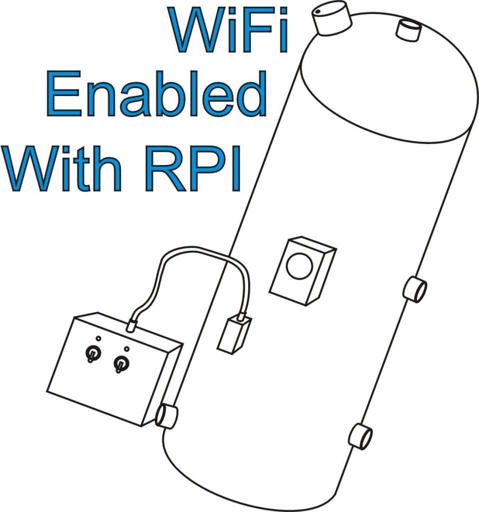
The present project is a WiFi enabled hot water tank thermostat. This is powered by a Raspberry Pi Zero which can be remotely controlled directly by VNC. This enables the water temperature to adjusted and I have included a facility to switch the electric immersion heater on and off. We have very rarely used the immersion heater but with solar power coming to our house it may be advantageous to switch from gas to electricity.
(It should be noted that we have a “conventional” as opposed to a “combi” boiler here and this project only makes sense for that type of system.)
Gerneral arrangement
On the input side, the Pi Zero connects to a couple of one wire DS18B20 temperature sensors and a couple of manual override switches. On the output side, there are a couple of 16 amp relays, one to act as the thermostat contacts and one to operate the immersion heater. There are also a few indicator LEDs.
Circuit diagrams
Circuit 1
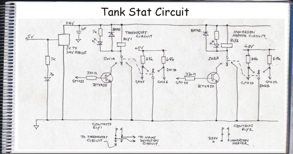
The first diagram shows the relay which reproduces the contacts of the old mechanical thermostat and the relay which turns on the immersion heater. The relays are Finder type 40.61S rated at 16 Amps. I got confused when I purchase these and didn’t notice they had 24v coils rather than the 5v I wanted. To get over this, I used an MT3608 voltage step up module (which are, fortunately, cheap as chips – the fried variety!) The override toggle switches enable off, permanently on and controlled (by the Pi) to be selected. The second pole of each switch is connected to a couple of GPIOs so that the Pi knows qhich position is selected and can indicate this remotely.
Circuit 2
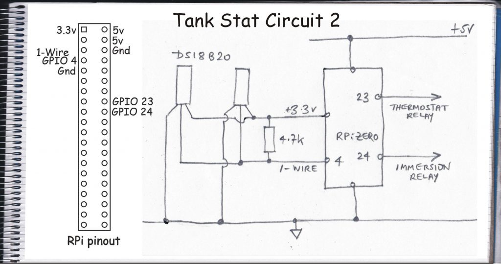
The second diagram shows how the 1-wire DS18B20 temperature sensors connect to the Pi. I used two sensors as I wanted to see how the temperature in the tank varied from top to bottom and where the best place for the sensors might be. I was expecting a bit of a gradient (hot water rises etc.) but there didn’t seem to be much of a one. (As an aside, these sensors can be bought for a range of prices. It would appear from reviews the the cheap ones may be [Chinese?] clones and are often unreliable especially in the uncased version. I tested three of these together and, in my case, they all registered more or less the same temperature within 0.1 of a degree or so. Therefore, I felt these would probably be OK even if the absolute temperature was half a degree off which for this application is not a problem.)
Circuit 3

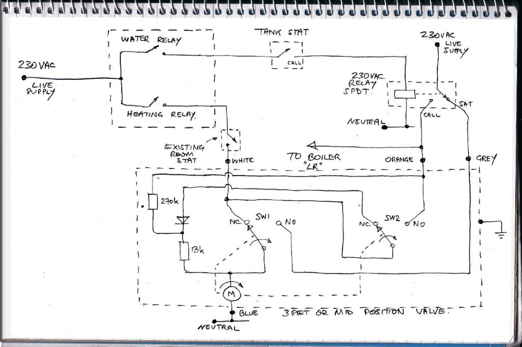
The third diagram shows a circuit which I guess is not strictly necessary but it did enable me to be a little bit innovative (I think). Refer to the original boiler circuit below. A great deal of the lower part of the diagram is taken up by the internal circuit of the three port valve (which switches hot water from the boiler between the hot water tank and the room radiators etc.) Above you can see the contacts of the original mechanical tank stat. Then water in the tank is timed to be heated, 230vac will appear across the contacts, if they are not closed. Thus if the presence of this voltage could be detected, it would be possible to deduce that the boiler circuitry was timed for water to be heated but the set temperature had been reached already.
Original boiler circuit
Such a device which detects the presence of 230vac and produces a 3.3v totally isolated signal in response seems to be hard to find especially one which draws very little current from the mains voltage. My solution is to use 230v neon indicator to generate light which is detected by a phototransistor. (The isolation should be several thousands of volts!) Current in the neon is limited by the two 47k resistors. The neon is like a voltage regulator – it always tries to adjust the current through it so that the voltage across it is 85 volts. (230 – 85)/94 = about 1.5mA (Ohm’s law etc.) So the current draw on the mains is very low.
The output of the phototransistor will be 50 Hz AC so will need to be rectified to DC by a couple of diodes. The circuit is rather high impedance (a different phototransistor collector resistor value might have helped here, say 1k?) so I have connected the signal to MOSFET version of the 555 timer (my favourite!) wired as a Scmitt trigger. This produces an output which is either on or off but nothing in between (at least which would register at the speed of these circuits). With a supply of 3.3v, in my experience, its output is quite a bit less than the expected 3.3v so to be certain that the Pi correctly reads the circuit, I added a ZTX450. This produces a high output when 230vac is present.
The only downside, for me is that, because of the high impedance, when the 230vac turns off, the output does not change for about 10 seconds. This is the time taken for the 0.01uF smoothing capacitor to be discharged by the 1M resistor. This is, however, not particularly important in this application.
Construction
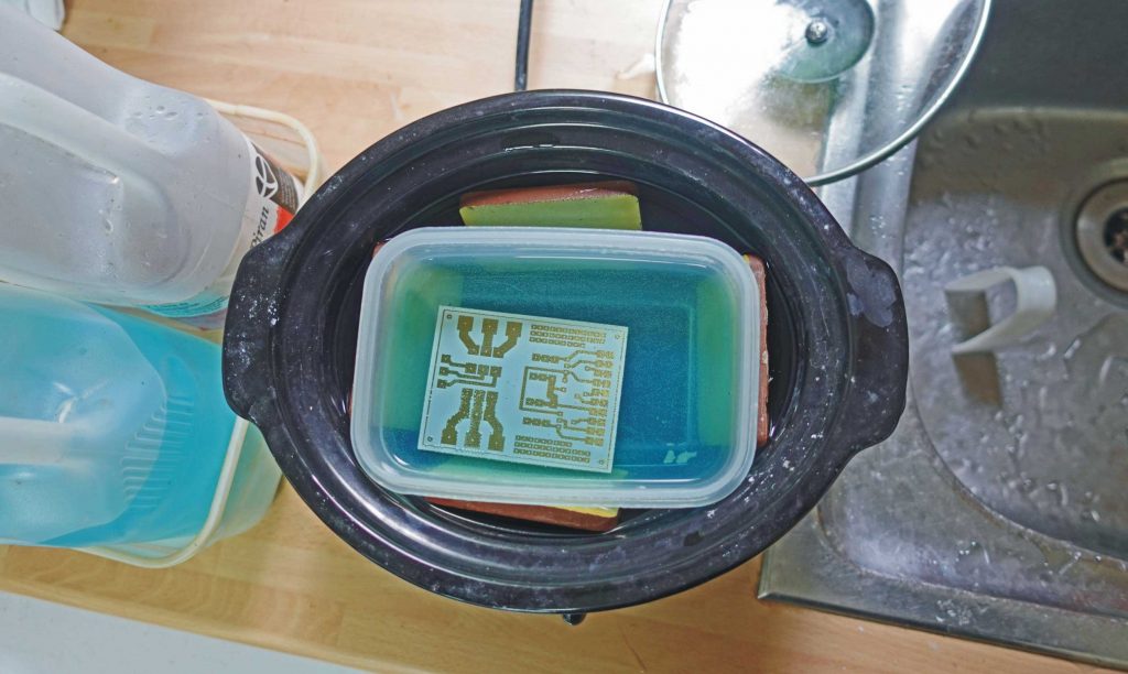
I have designed a PCB for the main circuit, keeping the mains 230v as far away from the low voltage stuff and making the tracks wide enough for 15A (I hope). The connector to the 40 pin header on the Pi is made from strip board (Veroboard as it is often called). I used a Stanley knife to make a break in the tracks between the 20 pin halves of the headers. I use two 20 pin single bank twenty pin headers (as that’s what I had!). I enlarge holes in the strip board to 1.5mm and pass flexible cables though the holes and pass the strands back up through the relevant holes for soldering. This prevents the soldered wire from breaking if they are wiggled about. (I use flexible wires stripped out of “alarm cable”. A drum of this is very cheap, provides eight different colours and the isulation is heat resistant so doesn’t strip back when soldered.
I used a short piece of aluminium square bar drilled out to 6mm to hold the temperature sensors with the pieces of bar strapped to the tank with wire passing round the tank with a spring to hold it tight.
I have 3-D printed the case in PETG which should be stable enough at the temperatures found beyond the tank insulation. The labels on the case are printed in reverse (so the printing is on the back of the film) on printable film and held in place with spray mount.
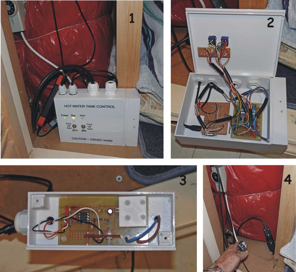
Pic 1 shows the finished unit temporarily powered by a battery. Pic 2 shows the inside of the case. The Pi Zero is under the piece of strip board to which the headers connecting to the Pi are soldered as mentioned above. Pic 3 shows the 230vac detector circuit. This was a bit of an after thought and it fits into its own box screwed to the end of the main case. The neon and phototransistor are under the 3-D printed square which aligns the components, keeps out stray light and keeps from accidental contact with the 230v. Pic 4 shows the mounting for one of the sensors on the tank (which needs more thermal insulation).
Software
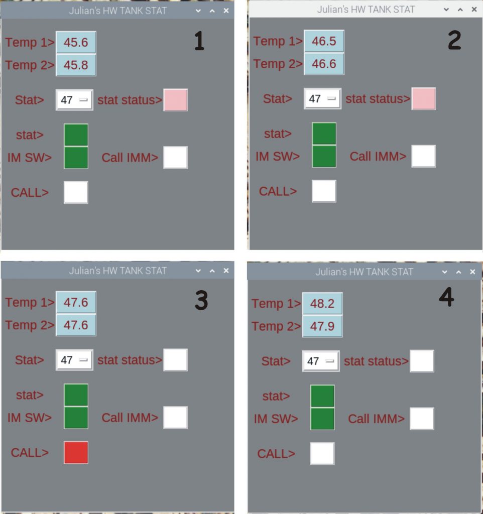
The software running on the Pi is in Python 3 using the Tkinter graphic interface. The four screen shots above show what happens as the hot water tank heats up. You can see that 47 degC has been chosen for the stat. This temperature at the tank produces a comfortable bath temperature without needing to add cold water. (If using a lot of hot water you would probably need a higher temperature or the tank would run out. For us, this is not the case. Other areas of the house have independent hot water supplies and anyway, my wife prefers a shower!)
Amongst other features shown on the interface screen are the temperatures registered by the sensors, and the status of the override switches – green means the swiches are in software controlled mode.
In pic 1, the pink square shows the temperature has not reached the desired level and the stat contacts are closed. In pic 2, the temperature is nearly there. In pic 3 the temperature has been reached, the pink square turns white (contacts open) and the “CALL” square turns red showing the stat contacts are ope but that the current boiler hot water period has not yet run out. In pic 4 the red sqare turns white – the timed period has expired. There is slight overshoot on the water temperature.
Current version of the Python software
# tankstat_6
# read ds18b20
# switch boiler, immersion heater etc.
# 06.06.23
# sensor reading credit to the hackster below!
# www.hackster.io/vinayyn/multiple-ds18b20-temp-sensors-interfacing-with-raspberry-pi-d8a6b0
# (my labels on sensors)
# one wire identifications:
# three: 28-062140cb1458
# two:   28-062140e4fd75
# "temp" is "three"
# "temp1" is "two"
# GPIO 23 is immersion heater
# GPIO 24 is tank stat
# GPIOs 5, 6 detect SW1 (tank stat)
# GPIOs 27, 22 detect SW2 (immersion)
# GRIO 26 mains detection
# GPIO 12 mains detect LED
import os
import glob
import time
import datetime
from datetime import datetime
from tkinter import *   #GUI
import RPi.GPIO as GPIO
GPIO.setmode(GPIO.BCM)
GPIO.setwarnings(False)
# outputs for power relays
GPIO.setup(23, GPIO.OUT)
GPIO.setup(24, GPIO.OUT)
# mains detect LED
GPIO.setup(16, GPIO.OUT)
GPIO.setup(5, GPIO.IN)
GPIO.setup(6, GPIO.IN)
GPIO.setup(27, GPIO.IN)
GPIO.setup(22, GPIO.IN)
GPIO.setup(26, GPIO.IN)
GPIO.output(23,0)
GPIO.output(24,0)
GPIO.output(16,0)
global time_on, max_im_time, test_flag
time_on = 0
test_flag = True
max_im_time = 1  # max time on on minutes
# These  lines mount the device:
os.system('modprobe w1-gpio')
os.system('modprobe w1-therm')
base_dir = '/sys/bus/w1/devices/'
# Get all the filenames begin with 28 in the path base_dir.
device_folder = glob.glob(base_dir + '28*')[0]
device_folder1 = glob.glob(base_dir + '28*')[1]
device_file = device_folder + '/w1_slave'
device_file1 = device_folder1 + '/w1_slave'
#reading temperature from folder
def read_temp_raw():
f = open(device_file, 'r')
lines = f.readlines()
f.close()
return lines
def read_temp_raw1():
g = open(device_file1, 'r')
lines1 = g.readlines()
g.close()
return lines1
#converting the temperature data to human readable form
def read_temp():
lines = read_temp_raw()
while lines[1].strip()[-3:] != 'YES':
lines = read_temp_raw()
equals_pos = lines[1].find('t=')
temp_string = lines[1][equals_pos +2:]
temp_c = float(temp_string) / 1000.0
return temp_c
def read_temp1():
lines1 = read_temp_raw1()
while lines1[1].strip()[-3:] != 'YES':
lines1 = read_temp_raw1()
equals_pos1 = lines1[1].find('t=')
temp_string1 = lines1[1][equals_pos1 +2:]
temp_c1 = float(temp_string1) / 1000.0
return temp_c1
set_temp = 22
BACKGROUND = "gray"
hysteresis = 1
# create the root window
root = Tk()
# modify the window
root.title("Julian's HW TANK STAT")
root.configure(bg = BACKGROUND)
# fill available screen space
# w, h = root.winfo_screenwidth(), root.winfo_screenheight()
# root.geometry("%dx%d+0+0" % (w, h))
root.geometry("400x400")
# create a frame
app = Frame(root)
app.configure(bg = BACKGROUND)
app.grid()
# blank row
blank_row = Label(app, bg = BACKGROUND)
blank_row.grid(row = 1)
temp_one_lab = Label(app, text = "Temp 1>", font = ("Arial", 16), fg = "maroon", bg = BACKGROUND)
temp_one_lab.grid(row = 2, column = 1)
temp_one_but =Button(app, text = "XXXX", font = ("Arial", 16), fg = "maroon", bg = "light blue")
temp_one_but.grid(row = 2, column = 2)
temp_two_lab =Label(app, text = "Temp 2>", font = ("Arial", 16), fg = "maroon", bg = BACKGROUND)
temp_two_lab.grid(row = 3, column = 1)
temp_two_but =Button(app, text = "XXXX", font = ("Arial", 16), fg = "maroon", bg = "light blue")
temp_two_but.grid(row = 3, column = 2)
# blank row
blank_row = Label(app, bg = BACKGROUND)
blank_row.grid(row = 4)
stat_lab = Label(app, text = "Stat>", font = ("Arial", 16), fg = "maroon", bg = BACKGROUND)
stat_lab.grid(row = 5, column = 1)
tank_stat_val = StringVar (app)
tank_stat_val.set("45") # initial value
thermostat_opt_men = OptionMenu(app, tank_stat_val, "15","20","30","31","32","33","34","35","36","37"
,"38","39","40","41","42","43","44","45","46","47","48","49"
,"50","51","52","53","54","55")
thermostat_opt_men.config(font = ("Arial", 14), fg = "black", bg = "white", width = 2)
thermostat_opt_men.grid(row = 5, column = 2, columnspan = 2, sticky = W)
stat_on_lab =Label(app, text = "stat status>", font = ("Arial", 16), fg = "maroon", bg = BACKGROUND)
stat_on_lab.grid(row = 5, column = 3, sticky = E)
stat_on_but = Button(app, text = "X", font = ("Arial", 16), fg = "white", bg = "white")
stat_on_but.grid(row = 5, column = 4, sticky = E)
# blank row
blank_row = Label(app, bg = BACKGROUND)
blank_row.grid(row = 6)
stat_status_lab = Label(app, text = "stat>", font = ("Arial", 16), fg = "maroon", bg = BACKGROUND)
stat_status_lab.grid(row = 7, column = 1)
stat_status_but = Button(app, text = "X", font = ("Arial", 16), fg = "white", bg = "white")
stat_status_but.grid(row = 7, column = 2)
imm_status_lab = Label(app, text = "IM SW>", font = ("Arial", 16), fg = "maroon", bg = BACKGROUND)
imm_status_lab.grid(row = 8, column = 1)
imm_status_but = Button(app, text = "X", font = ("Arial", 16), fg = "white", bg = "white")
imm_status_but.grid(row = 8, column = 2)
imm_sw_lab = Label(app, text = "Call IMM>", font = ("Arial", 16), fg = "maroon", bg = BACKGROUND)
imm_sw_lab.grid(row = 8, column = 3)
imm_sw_but = Button(app, text = "X", font = ("Arial", 16), fg = "white", bg = "white")
imm_sw_but.grid(row = 8, column = 4)
# blank row
blank_row = Label(app, bg = BACKGROUND)
blank_row.grid(row = 9)
call_lab = Label(app, text = "CALL>", font = ("Arial", 16), fg = "maroon", bg = BACKGROUND)
call_lab.grid(row = 10, column = 1)
call_but = Button(app, text = "X", font = ("Arial", 16), fg = "white", bg = "white")
call_but.grid(row = 10, column = 2)
def imm_switch():
global time_on
current_time = datetime.now()
if imm_sw_but.config('bg')[-1] == "red":
imm_sw_but.config(bg = "white", fg = "white")
GPIO.output(23,0)
time_on = 0
else:
imm_sw_but.config(bg = "red", fg = "red")
GPIO.output(23,1)
time_on = current_time.hour * 60 + current_time.minute
imm_sw_but.config(command = imm_switch)
def task():
global time_on, max_im_time
current_time = datetime.now()
total_mins = current_time.hour * 60 + current_time.minute
print(total_mins)
if total_mins >= time_on + max_im_time:
GPIO.output(23,0)
imm_sw_but.config(bg = "white", fg = "white")
try:
t0 = read_temp()
print(t0)
t1 = read_temp1()
print(t1)
except TypeError:
print("Error!")
set_temp = float(tank_stat_val.get())
if t0 > set_temp:
GPIO.output(24, 0)
GPIO.output(23, 0)
imm_sw_but.config(bg = "white", fg = "white")
stat_on_but.config(bg = "white", fg = "white")
if t0 <= set_temp - hysteresis:
GPIO.output(24, 1)
stat_on_but.config(bg = "pink", fg = "pink")
temp_one_but.config(text = round(t0, 1))
temp_two_but.config(text = round(t1, 1))
sw2a = GPIO.input(5)
sw2b = GPIO.input(6)
sw1a = GPIO.input(27)
sw1b = GPIO.input(22)
mains = GPIO.input(26)
if sw1a == 1 and sw1b == 1:
stat_status_but.config(bg = "white", fg = "white")
if sw1a == 1 and sw1b == 0:
stat_status_but.config(bg = "green", fg = "green")
if sw1a == 0 and sw1b == 1:
stat_status_but.config(bg = "orange", fg = "orange")
if sw2a == 1 and sw2b == 1:
imm_status_but.config(bg = "white", fg = "white")
if sw2a == 1 and sw2b == 0:
imm_status_but.config(bg = "green", fg = "green")
if sw2a == 0 and sw2b == 1:
imm_status_but.config(bg = "blue", fg = "blue")
if GPIO.input(26) == 1:
call_but.config(fg = "red", bg = "red")
GPIO.output(16,1)
else:
call_but.config(fg = "white", bg = "white")
GPIO.output(16,0)
global test_flag
#if test_flag == True:
#test_flag = False
#GPIO.output(16,1)
#elif test_flag == False:
#test_flag = True
#GPIO.output(16,0)
root.after(1000, task)
root.after(1000, task)
root.mainloop()