What a great film 2001 is. After all these years, the technology depicted still looks futuristic and the action equals the best that today’s CGI can offer (I would go as far as to say it looks more real than CGI). The ape men don’t tally with the latest theories about hominid evolution and the ending still slightly baffles me (I’ve read various explanations but like the definition of existentialism they never seem to stick). Nevertheless, it is one of my favourite films.
I have wanted to try to emulate the HAL 9000 computer interface with the famous glowing red eye for a long time and now, at last, I’ve gone and done it! In this 3D-printed project, HAL’s voice is generated using an Adafruit Feather and a Musicmaker Featherwing combination. An initial program enables HAL phrases to sound at random times. The Feather I am using has built in WiFi so it would be possible to control the unit remotely.
The lens is from an old slide projector but an old 35mm camera lens would do. The unit has been scaled to work with the dimensions of the lens and is about half the size of the original, I would guess. Also, the size would be determined by the maximum size which can be printed on my printer and some of the component parts are right on the limit
It took about fifteen hours to print the case! Also, it’s quite close to the edge of the plate. It could only have been bigger if the print had been rotated by forty five degrees and then not by much.
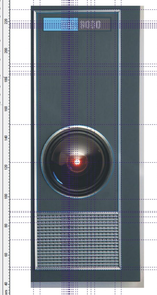
In order to design the case for HAL, I borrowed an image from an ad for a very expensive HAL reproduction and loaded it into a 2D graphics program, in this case a very old version of CorelDraw (9) which I have used for many years. I could proportion the image so that the diameter of the lens matched my lens. Then I could place guidelines on the important parts of the image, remove the image and draw the front components snapping the lines to the guides. I tend to design things as I go along so I decided to print the main part of the case first and go from there.
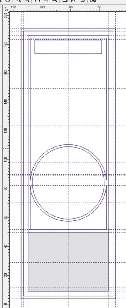
Having done this, I designed the front to be a tight fit into the case. The front would be in the form of a shallow box deep enough to fit into the case leaving half an inch for a surround of 1/2 inch by 3.2 mm (1/8 inch) aluminium strip. (I had made the case 3.2 mm thick so that the surround would be flush.
Since the front of the front (as it were) would actually need to be the bottom of the print which is not always the best quality (at least when I print), I printed out a front facing panel and the grille separately. I designed the grille with too fine a pitch and it didn’t print out well so I enlarged it in Cura (the program which turns the 3D design into a file to load into the printer) and trimmed it to fit with a fine saw.
(Because neither I nor my software is very sophisticated, the picture below is assembled from screenshots which explains why the 3D views of the parts are not consistent.)
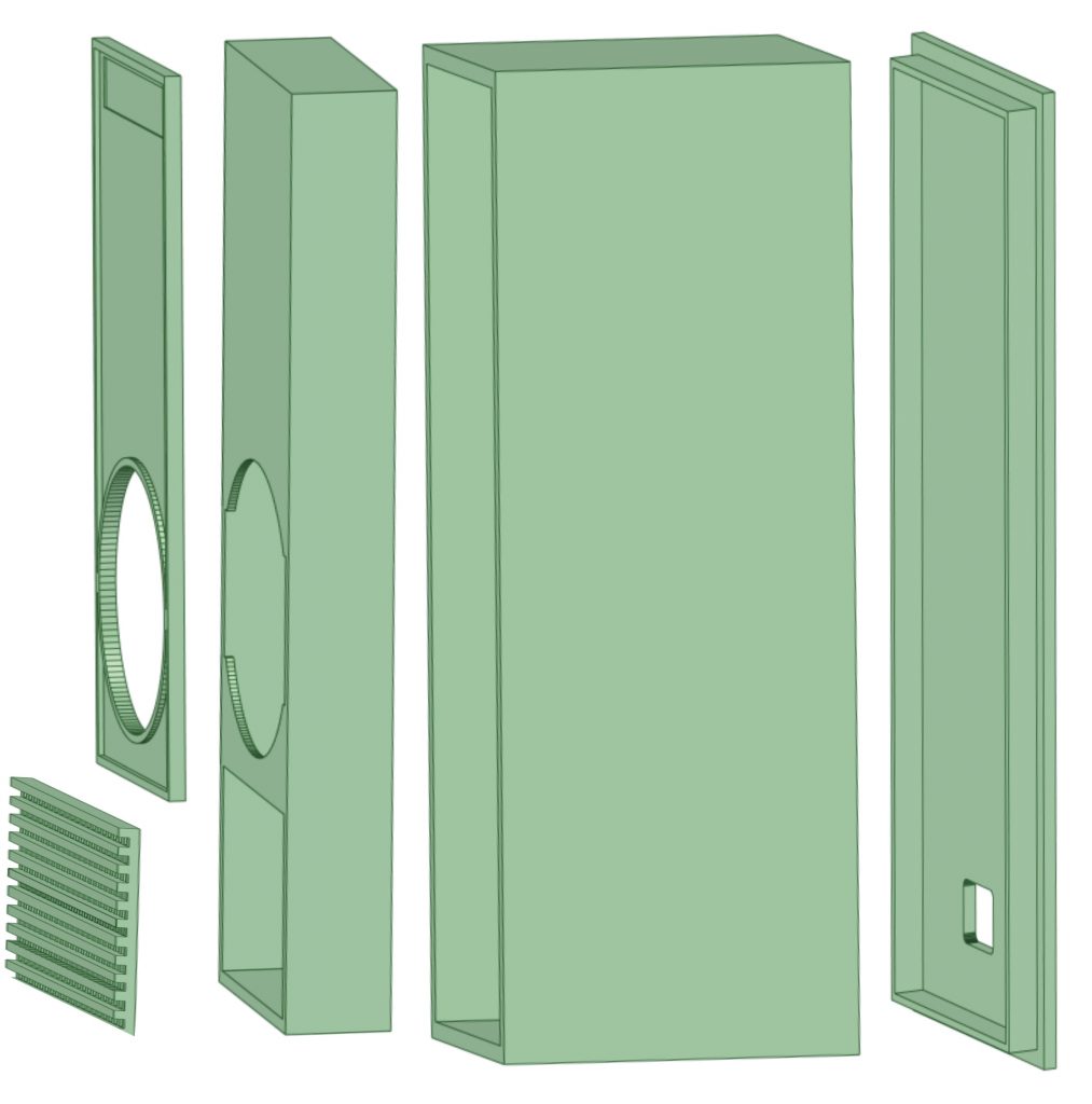
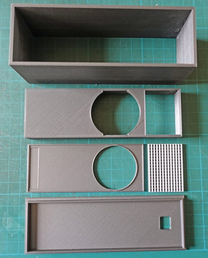
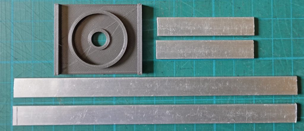
Below are the main parts for the case printed in dark metallic grey and pale grey for the grille. Note there is a small depression on the front panel to locale the HAL 9000 logo. The back has a cut out for the USB programming/power lead.
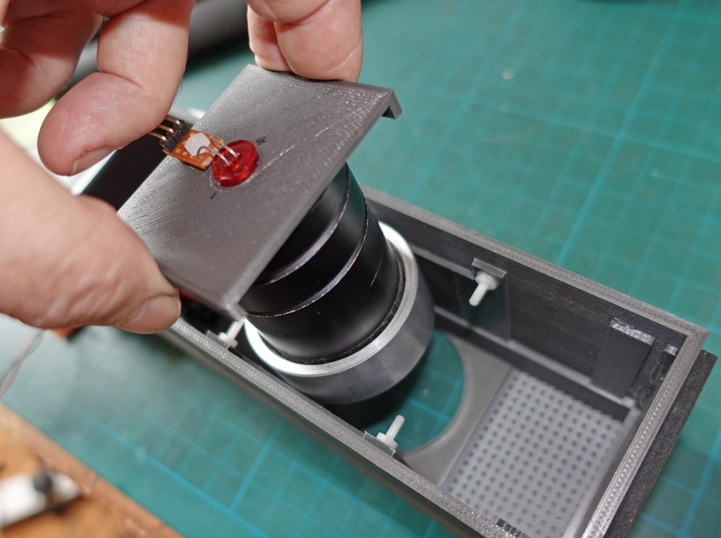
Below: Support for rear of lens (it pushes onto the ring) together with push fit hole for 10 mm red LED. Also 10×3.2 mm aluminium decorative strip. This needs to be mitred.
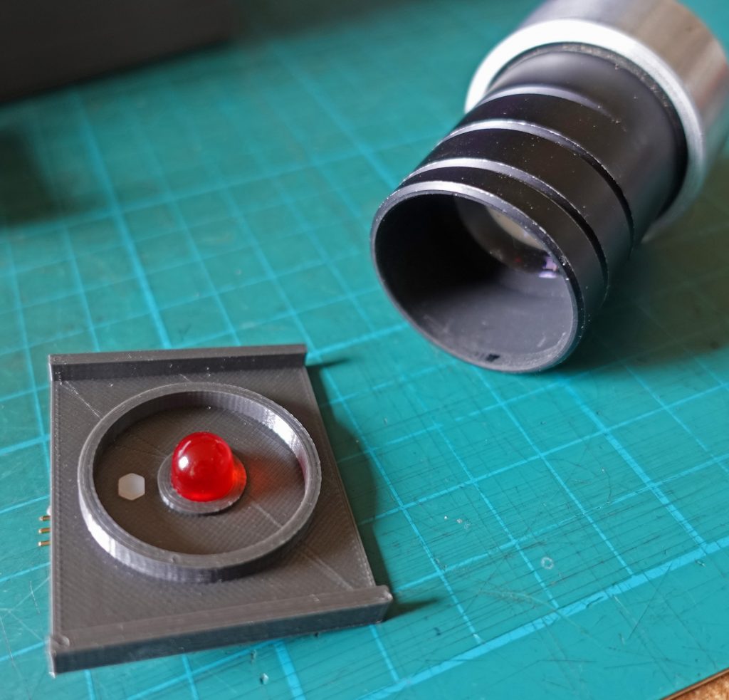
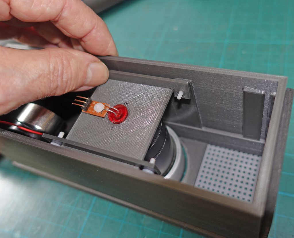
Below: Parts to retain lens and its support plate. How these work is shown later.
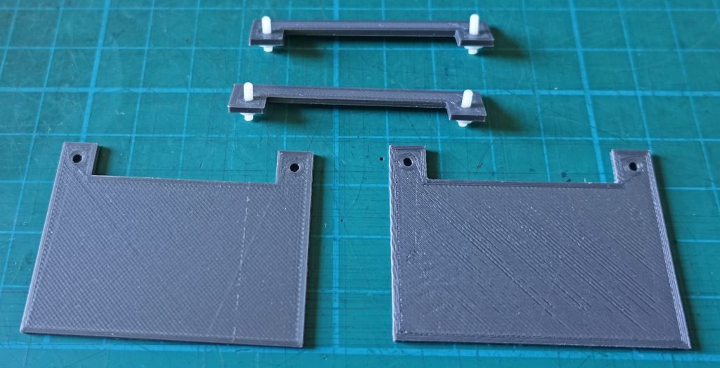
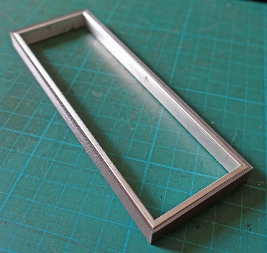
Below: The front is pushed into the case but only so far as to leave a space for the aluminium trim which will be flush with the decorative front panel when it is glued onto the front
Below: I printed a rectangle of the right inside dimension to hold the mitred pieces of aluminium trim. I used this to hold the trim accurately in place as it was Araldited into position. I intended to discard it when the glue had set but I preferred seeing just the edge of the aluminium trim so I have left it in place.
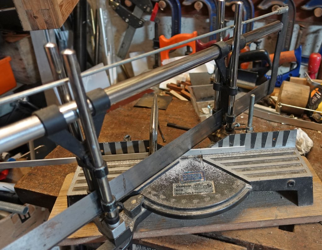
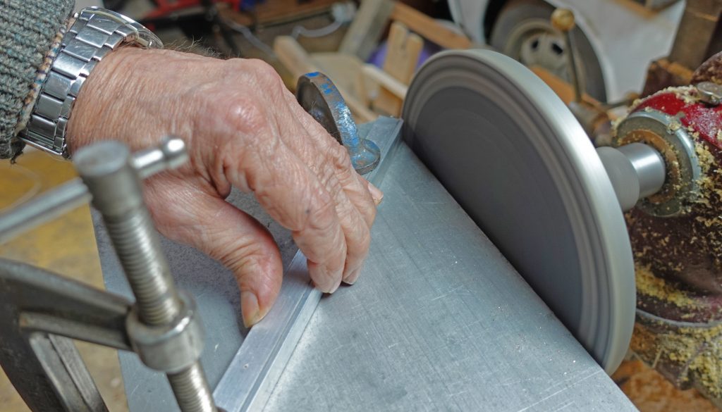
Above: I used a mitre saw to cut the pieces of aluminium a little oversize then (below) I trimmed them to as near to exact as I could with a sanding disc. This, in many ways, is the trickiest part of the build. I could have done better on one bit but at my time of life you sometimes have to say enough is enough!
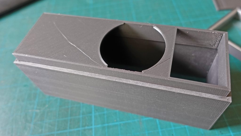
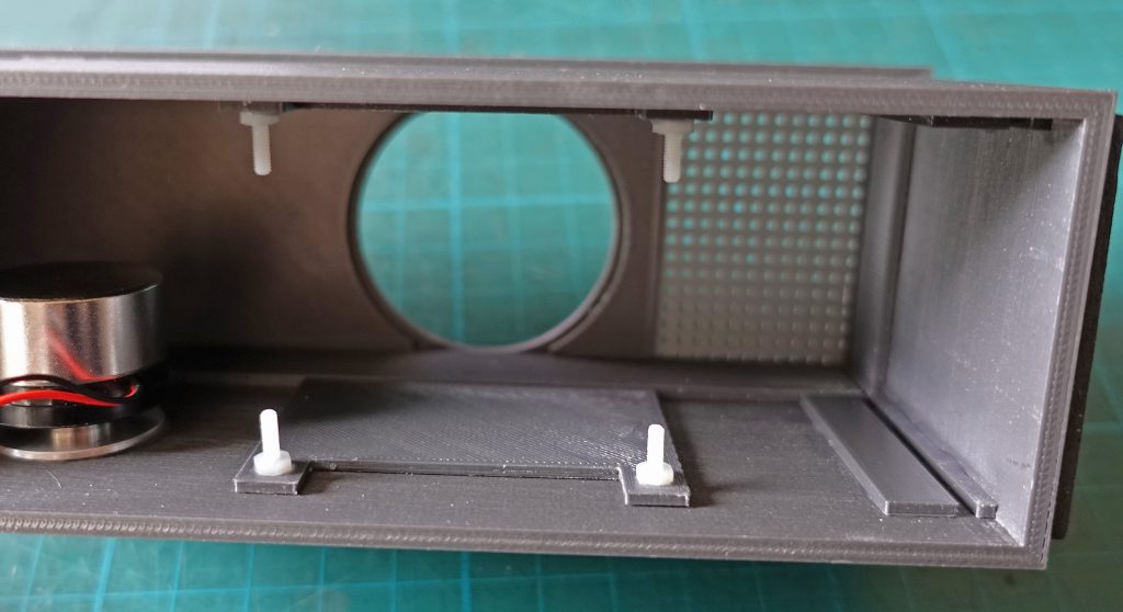
Below: I glued the pieces which locate the lens into the case. The nylon screws hold the pieces which lock the lens assembly in place (see below). On the rigt of the picture (the bottom of the case) are runners into which the board holding the Feather slides, I had intended to put the speaker in the bottom (behind the grille, as you would expect) but I decided to try a surface speaker which needs to be glued to the case so the speaker goes where the Feather would have been and vice versa.
Below: I drafted the HAL9000 logo on CorelDraw9 (it’t ver old but still effective!) In reverse and printed it out on transparent inkjet film so providing a shiny and scratch-resistant surface when turned round. I cut a piece of white plastic insulating tape and stuck it to the front panel where I had printed in a slight depression. Then I stuck on the logo using spray mount adhesive.