
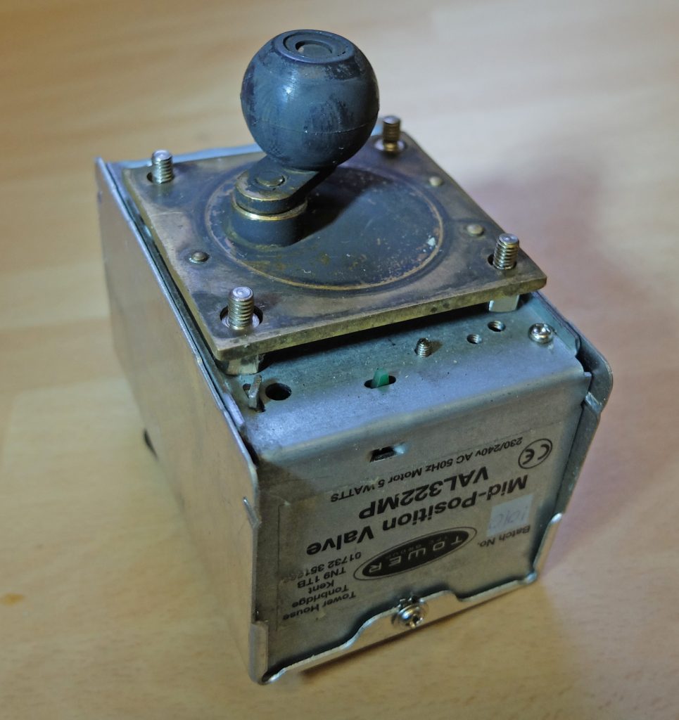
This is how the 3-port central heating valve works. The valve consists of a brass body with three compression fittings: one in and two out. Water flow is controlled by a rubber ball can block either outlet or take up a position which allows water to flow through both outlets. The position of the ball is controlled by a motor unit which is equipped with a couple of microswitches so that it “knows where it is” (knowing where you are at any given time is essential in any control system!)
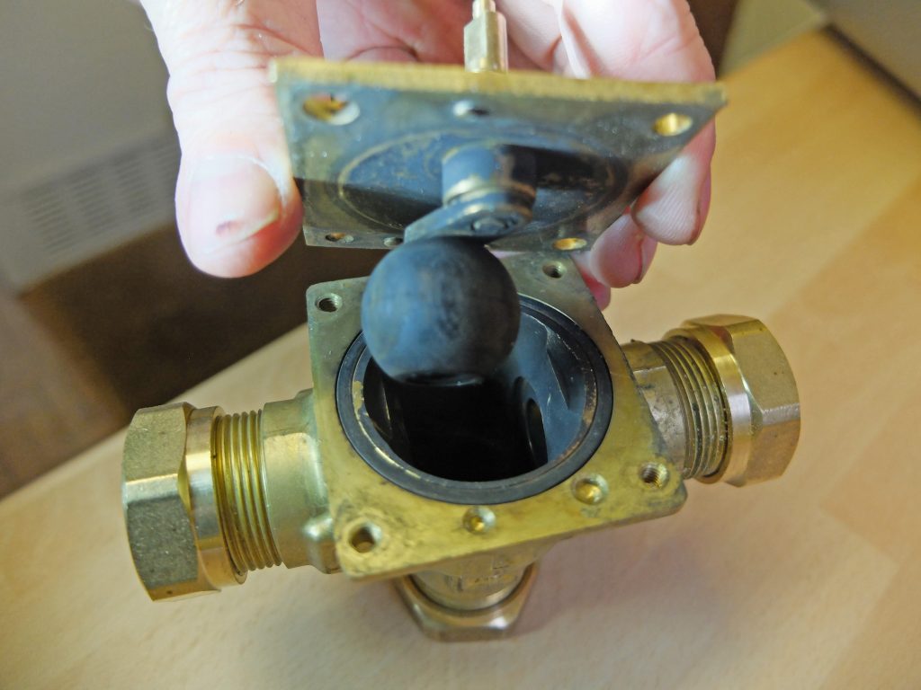
Above: The ball can turn on its lever which it will do under the movement of the water. This evens out wear which could lead to inefficient sealing. Also, a ball is streamlined increasing flow efficiency. Also being a non-precision fit it can accommodate bits or grot and such that are likely to be in the water without failure.
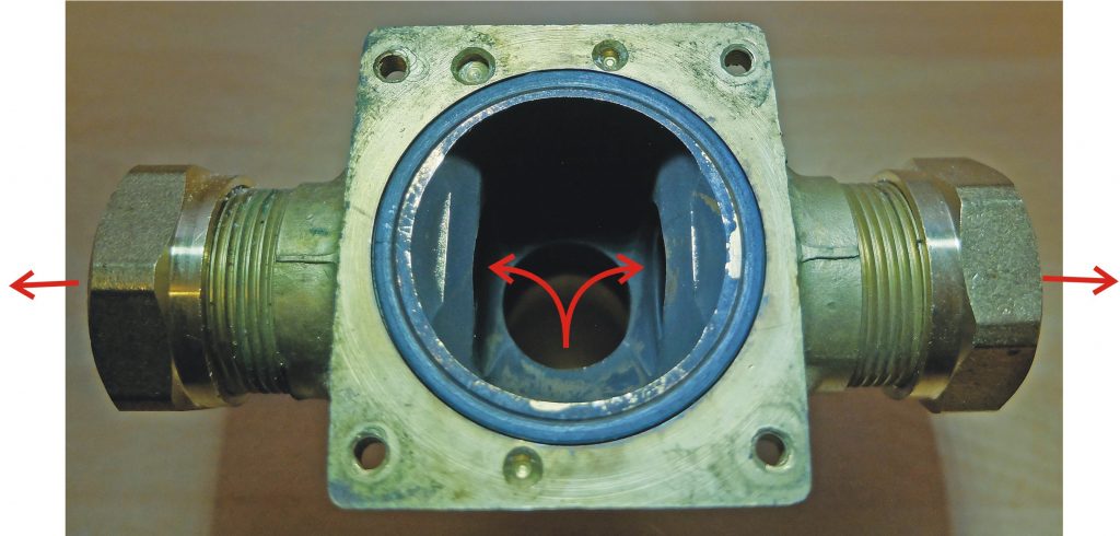
Above: By rotating the lever through a very small angle (10 degrees?) the ball can close off either of the two outlet ports. If the ball is in the mid position, water can flow through both outlet ports.
How it works: overview
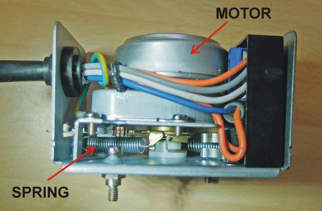
Above: When un-powered, a spring pulls the ball into a position where the port to the hot water tank is open and the port to the central heating radiators is closed. With the right electrical supply (to be described below), the synchronous/asynchronous motor runs and winds the lever into the other extreme position meaning that water is now supplied to the radiators and not to the hot water tank. (The motor is very weak, like a clock motor but there is sufficient reduction gearing to produce enough torque to overcome the spring and hold the ball in position.) At this point the motor stalls (stops turning because the ball is jammed up against the port.)
The motor is very weak, as has been mentioned, so consumes very little power, only a few watts. However, if is stalled it will dissipate more power and given that the valve is already at about 70 degrees C it will get hotter. This may contribute to a short life. Moreover, as will be described below, it is often the case, because of the design of the valve, that power will continue to be supplied to the motor even when the boiler itself is off (eg. at night).
The ingenious part of the design is how it achieves its mid position. With the right electrical supply, the motor will move through a central position and trigger two micro-switches one after the other. This establishes a position where, through the internal circuitry of the valve, the motor is supplied with DC rather than AC. This locks up the motor in the desired position!
Below: Details.
The thermostats have been left out to simplify the diagrams
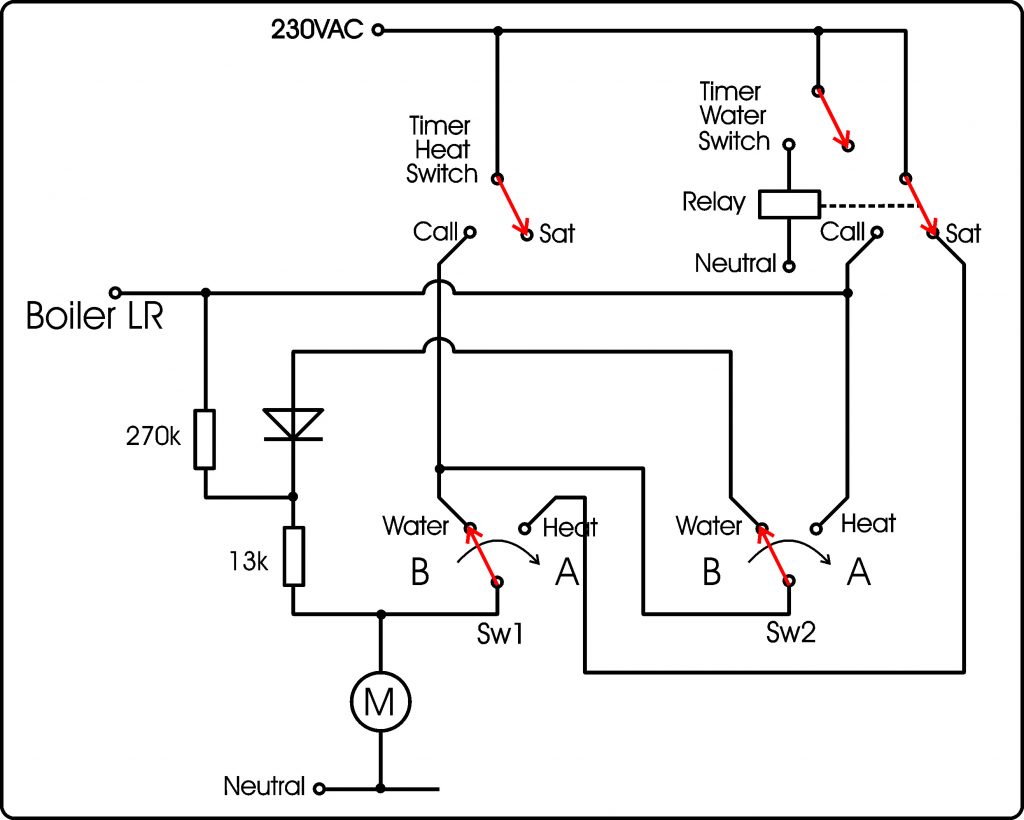
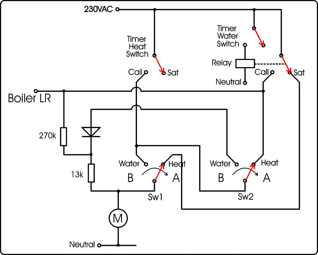
Above: In the first case there has been no power applied to the system. The spring has wound back the valve to the B position which corresponds to the valve being open for hot water to be pumped to the hot water tank and closed to the heating radiators. The timer is not asking for hot water or hot radiators.
If power is applied, with the positions of the switches as they are, nothing happens. The boiler is not turned on and the valve motor does not run.
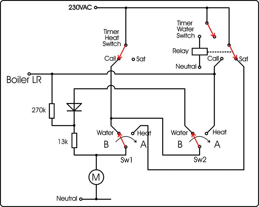
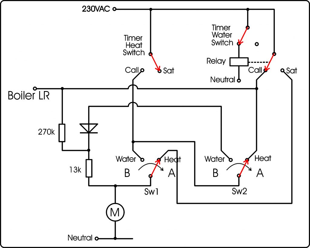
Above: Now if the timer calls for hot radiators, the valve motor starts to run driving the valve towards position A. At the start, however, the boiler is not on and nether Sw1 nor Sw2 have changed over.
Above: At some point, Sw1 changes but Sw2 has not yet changed. Sw1 is still supplying power to the valve motor but the boiler is still not running.
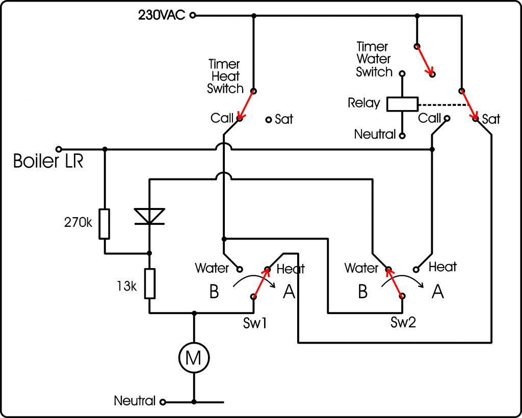
Above: The motor continues to drive the valve towards position A. At some point Sw2 changes over. Now power is supplied to LR and the boiler and pump fire up.
The valve motor continues running until it reaches position A with the water supply to the radiators and the route to the hot water tank closed. At this point the motor stalls. It is still receiving power but cannot turn.
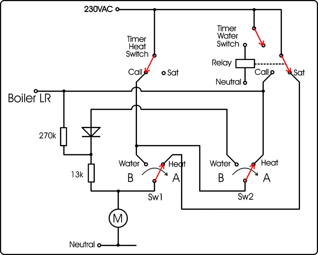
Above: Even if the timer calls for the radiators to no longer be supplied, although the boiler turns off (LR is no longer supplied with 230volts) the valve motor continues to be supplied and gets hot for no reason!
Above: If the timer now calls for hot water for the hot water tank, the power to the motor is cut and the spring returns the valve to position B.
It can be seen that at the end of the “heating day”, running the hot water for a brief period will turn off the valve motor and, perhaps, extend its life. This will only happen if the temperature of the water in the hot water storage tank is below the call temperature. However, anther way to achieve this would be to install a relay contact which would be operated by the timer to briefly interrupt the power to the tank stat.
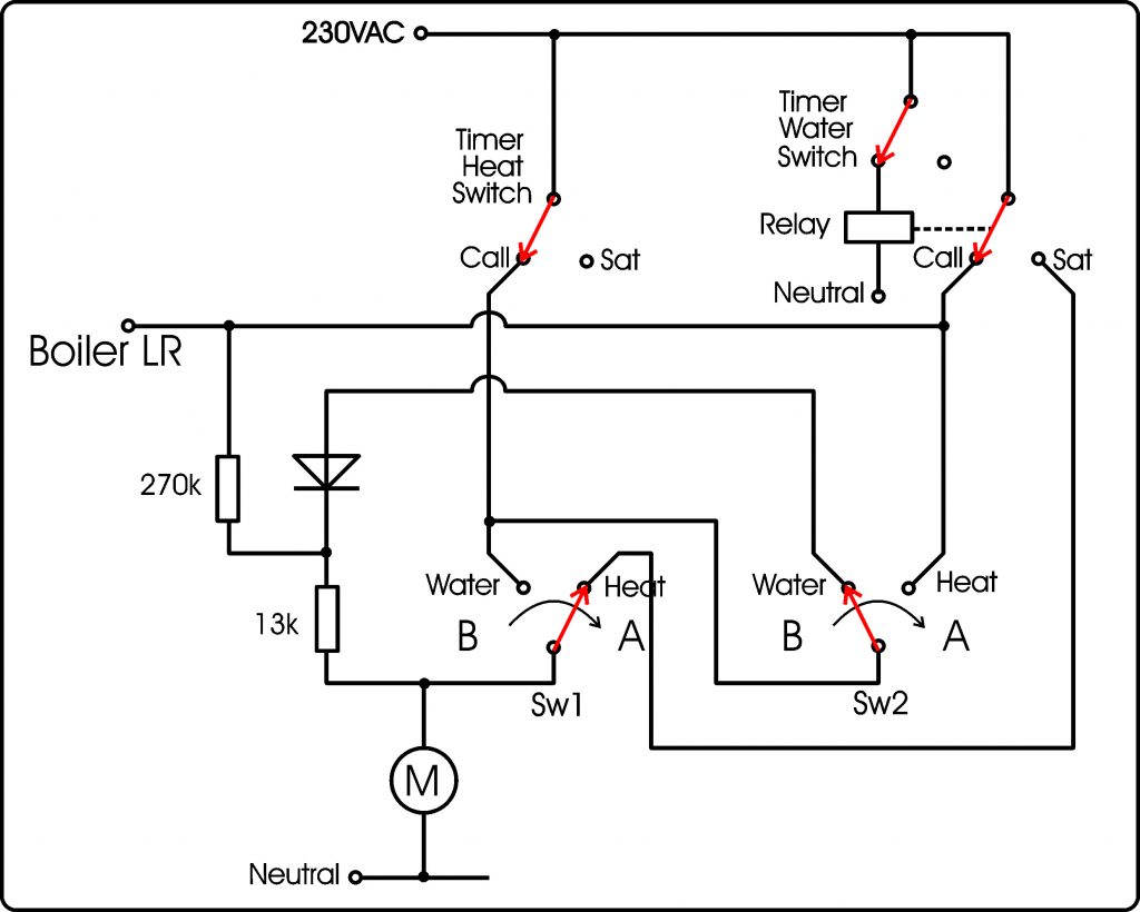
Above: This is the clever bit! If both hot water and hot radiators are required, this is where Sw1 and Sw2 come into play.
Suppose the call comes when the valve is in position B. The motor moves the valve until near the middle of its travel Sw1 changes. Suddenly the motor is supplied via Sw2 and the diode, that is with DC. This locks the motor in its mid position.
If the call comes when the valve is in position A, there will be no power to the motor and the valve will wind back on its spring until Sw2 changes and again, the motor will receive DC and lock.
In either case if the motor overshoots it will just return back to the mid position.
The 270K resistor supplies AC to the motor following it being fed DC to demagnetise any part which was tending to be permanently magnetised (which would upset the operation of the motor).