
The device described here is a part of my greenhouse monitoring and control project.
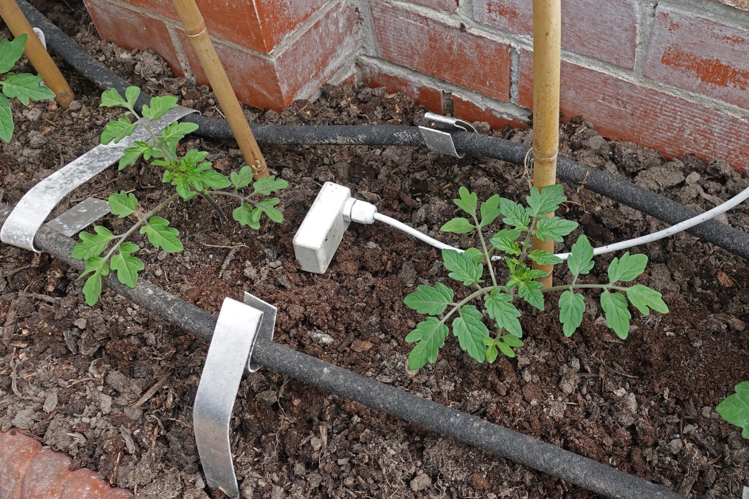
I want to monitor the dampness of soil in flower beds, pots and trays etc so I can implement an automatic watering system. Accurate measurement, perhaps in terms of percentage water content by weight, is difficult. The most obvious way is to measure the electrical resistance between two or more probes. Dry soil probably is very non-conductive, wet soil very conductive. However, I suspect the result is quite dependent on the concentration of salts which break into highly conductive ions. Soil will be full of such salts. (Pure water is not very conductive!) However, most of the plants we will be using will really suffer if the soil dries out, so this is the condition I need to be able to detect.
The circuit for my sensor uses my favourite 555 timer. The soil between two metal probes acts as the resistance in the capacitor/resistance timing network which governs the frequency at which the 555 pulses. The lower the resistance, the faster it pulses. The circuit has the advantage of first passing the current one way through the soil, then the other. This avoids a build up of gas at the electrodes/probes which is caused by electrolysis and will block the passage of electricity and spoil the accuracy of the sensor.
The pulses will be passed down a cable to the Feather which will measure their frequency. The signal should not be degraded passing own the cable as long as the length is “reasonable”. What this means, exactly, remains to be determined! To avoid any unwanted effects, back at the Feather, caused by putting the probes in the earth, the pulses will be electrically separated from the computer by opto-isolators (as described previously).
Circuit Diagram
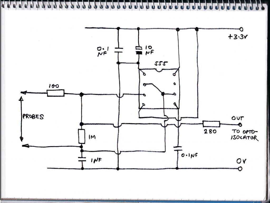
The circuit is pretty straightforward. It consists of a 555 timer chip configured to generate a continuous square wave with equal mark-space ratio (it’s output is off for the same time as it is on – although, especially at low voltage, that isn’t too precise but that’s not too important here). For an explanation of this circuit, see “IC 555 Projects” by EA Parr.
The 10M Ohm resistor is there so that the 555 produces square waves even if the probes are not in soil (otherwise the Arduino function returns zero which, in this context, should mean “waterlogged”. The 100 Ohm resistor avoids any problems if the probes are short-circuited. The 0.1 and 10 micro Farad capacitors are there to filter out hum pickup, electrical noise etc. The 280 Ohm resistor in the output feeds the input of the opto-isolator, which is located inside the main computer unit. It limits the current to the LED in the opto-isolator.
The value might need to be increased if there are losses in the cable connecting the sensor to the computer unit. Also an amplifier might be needed. I’ll have to see how it works.
Incidentally, the theory shows that the period of oscillation for the circuit (the time for “on” plus the time for “off”) should be 14 seconds for the 1 micro Farad capacitor and the 10 M Ohm resistor which gives time of 7 seconds for the “on” or “high” part. The Arduino typically returns about 7.5 million microseconds or 7.5 seconds. So the accuracy of the whole shooting match seems to be reasonable. However, ultimately, the output value will be calibrated to correspond with what I consider to be “dry”, “damp”, “wet” and “waterlogged”!
Test Program
The program to test the circuit is very simple. It just makes use of the pulseIn() function to measure the length of the pulse (the longer the pulse, the greater the resistance). The result appears on the serial monitor.
// soil dampness monitor
// 2.5.20
// dampness2
// measures a pulse length which is related to
// the reistance between two probes which, in turn
// is related to the dampness of the soil in which
// the probes are inserted (amongst other things)

int pulse_pin = 2;
unsigned long duration;

//----------------------------------------------
void setup() {

  // set pin up as input
  pinMode(pulse_pin, INPUT);

  Serial.begin(9600);
}

//-----------------------------------------------
void loop() {

  // measure a positive pulse in microseconds
  // the large number is the maximum time to wait for a pulse
  duration = pulseIn(pulse_pin, HIGH, 3000000);
  duration = duration / 100;
  Serial.println(duration);

}
Construction & Testing
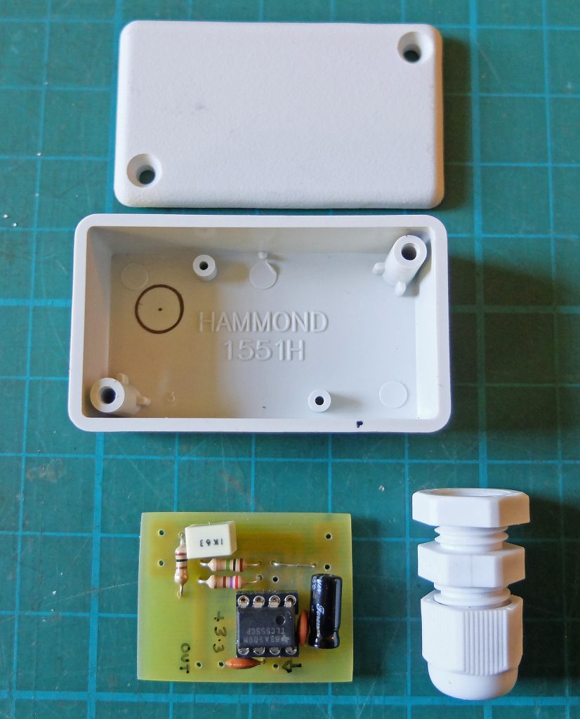
I made up a simple pcb for the circuit to fit in a small Hammond box with room also for a cable gland.
Currently, the probes will be made out of 1.5 tinned copper wire that I had to hand but ultimately I think I need to use stainless steel wire. The wire I used came on a reel. To make it straight, I put one end in a vice and pull the other end. If you pull hard enough, you will feel it give slightly as it passes the yield point. The molecules all slide slightly leaving the wire straight and slightly stiffer.
Rather than solder the wires to the pcb, I decided to use screw terminals. This will enable me to switch to stainless wires in the future (also stainless steel is difficult to solder).I used brass terminals cut from 5 amp terminal strips. The side to be soldered needs to be cleaned with 100 grit abrasive paper. Then apply a 100 watt soldering iron and when the brass has heated up, flow on some solder. Remove the soldering iron as quickly as possible to avoid the flux contained in the solder from burning off. Do the same for the pads on the pcb. Then using a piece of wire through the terminal to hold it in place, put the terminal on the pcb and apply the soldering iron until the solder melts on both the terminal and the pcb. Remove the soldering iron but continue to hold the terminal in place until the solder solidifies.
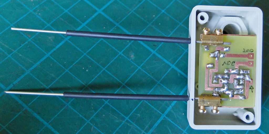
I covered the wires with shrink tubing (adhesive lined type) leaving 30 mm exposed. I feel it is important to get an indication of soil dampness just under the surface rather than just at the top. I need to see how this works out in practice.
Postscript: The 10M resistor turned out to be vital as without it, not only does the Feather return zero but it takes a great deal of time doing it. This means the (reasonably) regular pulse which the sketch causes the Feather to generate is delayed long enough to trigger the hardware watchdog timer (see here) which is designed to reset the Feather if it crashes. So if the sensor were to have been removed from the ground for more than about 30 seconds this would have happened