
The boiler has its own circuit involving a hot water tank thermostat, a single pole, double throw relay (SPDT), and a three port valve which switches the hot water between heating and hot water.
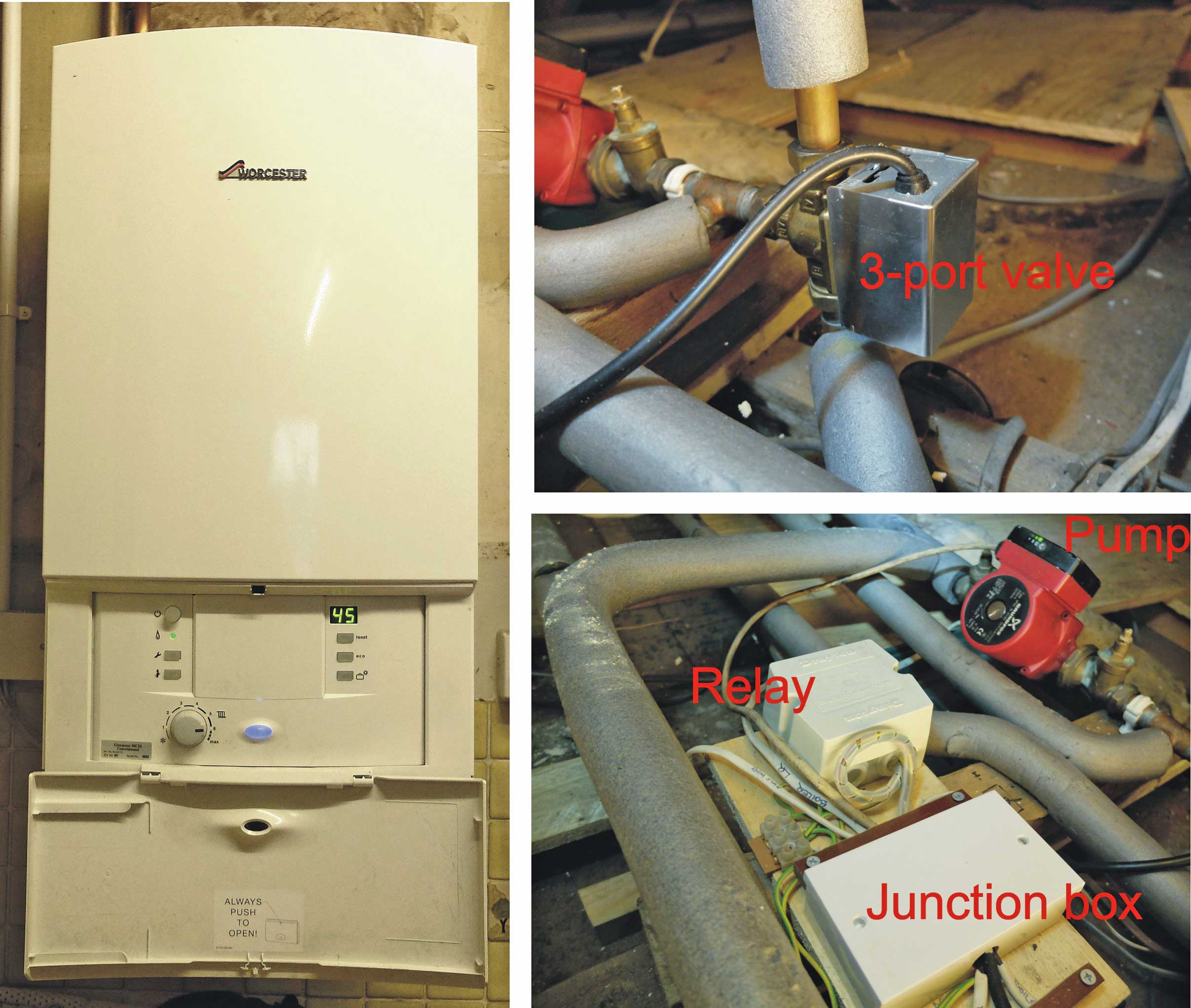
My boiler is a relatively modern Worcester non-combi model. It’s a non-pressurised system with a header tank in the roof. The connections to it are straightforward. They are 230 VAC live and neutral supply, live and neutral to the pump (the boiler takes care of when the pump should run) and a control input labelled “LR”. When this is supplied with 230 VAC live, the boiler runs. (As nearly always there is also a safety “earth” connection.) Also in the mix is a three port valve which can send hot water to the hot water cylinder or the radiators or both. In addition there is a tank stat and relay and in the original system, a room stat which is in what has become the utility room and which tends not to be heated, so it is not in a very useful place.
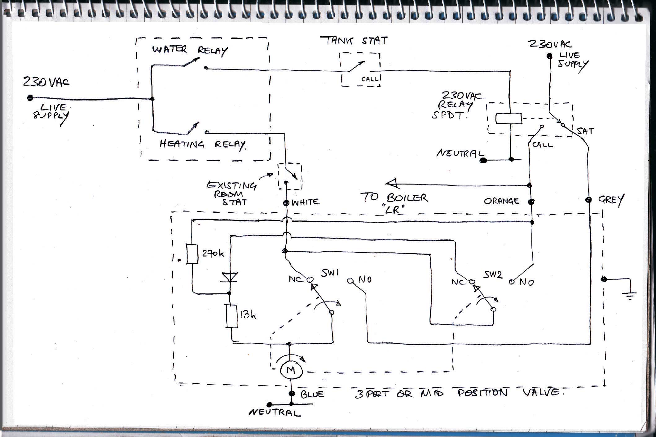
The circuit is straightforward (except for the detailed operation of the valve which channels hot water from the boiler to the heating system or the water heating systems or both as required). The room stat and the water tank stat are in series with the timer switches for their respective circuits. If either or both timer switches and thermostat switches are closed, 230VAC gets through to the boiler “LR” connection and the boiler runs and also switches on the pump. However, it is a little more complicated as the 230VAC only gets through to LR on the boiler after passing through a relay and the switching inside the valve.
In my installation, I have kept the room stat but I keep it set to be always on and the control is by the TMP102 sensor described on the previous page. The water temperature is still controlled by the mechanical tank stat. I could have replace this with another TMP102 or similar but I don’t feel the need to remotely adjust the hot water temperature, so I have left it in place.
The circuit in a way revolves around the three port, or mid position or 5-wire valve as I have heard it called. The colours, orange, grey and so forth refer to the leads from the valve and seem(?) to be standard. As mentioned above, the operation of the valve is subtle and is described in detail later. It has a sort of design flaw (which will be detailed in the section devoted to the operation of the valve) which could be the reason for their lack of reliability I have experienced. In brief, the valve motor receives current even when the boiler is off (for example over night). This wastes some electricity and causes the motor to always be hot which probably shortens its life. There are ways to get over this but it adds complexity.
In an installation, the valve and the relay will probably be close together. Quite a large junction box at this point is needed to connect up all the wires. I have used a standard twin-gang surface mount box and lid with a screw terminal connector strip inside and a couple of strips of Tufnol secured with nylon nuts and bolts to act as cable clamps (you can just see them in the picture above).
The relay is a fairly hefty unit, probably quite old, which came with the house. If I was starting from scratch I would probably make a PCB with a PCB relay and connectors etc. custom designed for the connections required. However, you’ve got to stop somewhere!
Ours is a fairly large rambling house and a single thermostat will not do a good job of controlling the system. Radiator stats do a reasonable job but what is really needed is motorised valves on radiators or at least on zones. That way rooms which may be out of use on certain days etc. will not be needlessly heated. This gets fairly complex and expensive but is a project I have in mind. I have made some progress towards this and it is the subject of a future page (or you could go to mr-r.co.uk).
Taking no chances
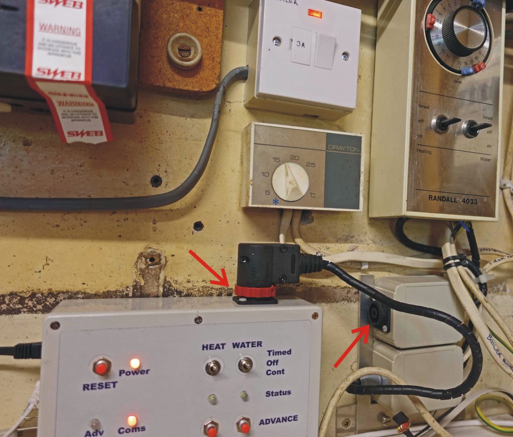
I have left the old mechanical timer in place in case things go wrong or I want to modify my new timer. By switching the Clifcon plug (red arrow) over to the socket (second red arrow) the timer function switches over to the old device.
The next page details timer and control software or here for the Watchdog to prevent hangups.